Copyright © 2008-2009 OW2 Consortium
This work is licensed under the Creative Commons Attribution-ShareAlike License. To view a copy of this license,visit http://creativecommons.org/licenses/by-sa/2.0/deed.en or send a letter to Creative Commons, 559 Nathan Abbott Way, Stanford, California 94305, USA.
- Preface
- 1. Introduction
- 2. Principles
- 3. Cluster configuration
- 4. Cluster and domain management
- 5. Tooling
- 6. Examples
- 7. Troubleshootings
- A. Appendix
At first, this guide gives an overview of the Java EE clustering principles. Afterwards it describes how to set up clustering in the JOnAS application server and how to manage it. Finally some tools and examples are presented.
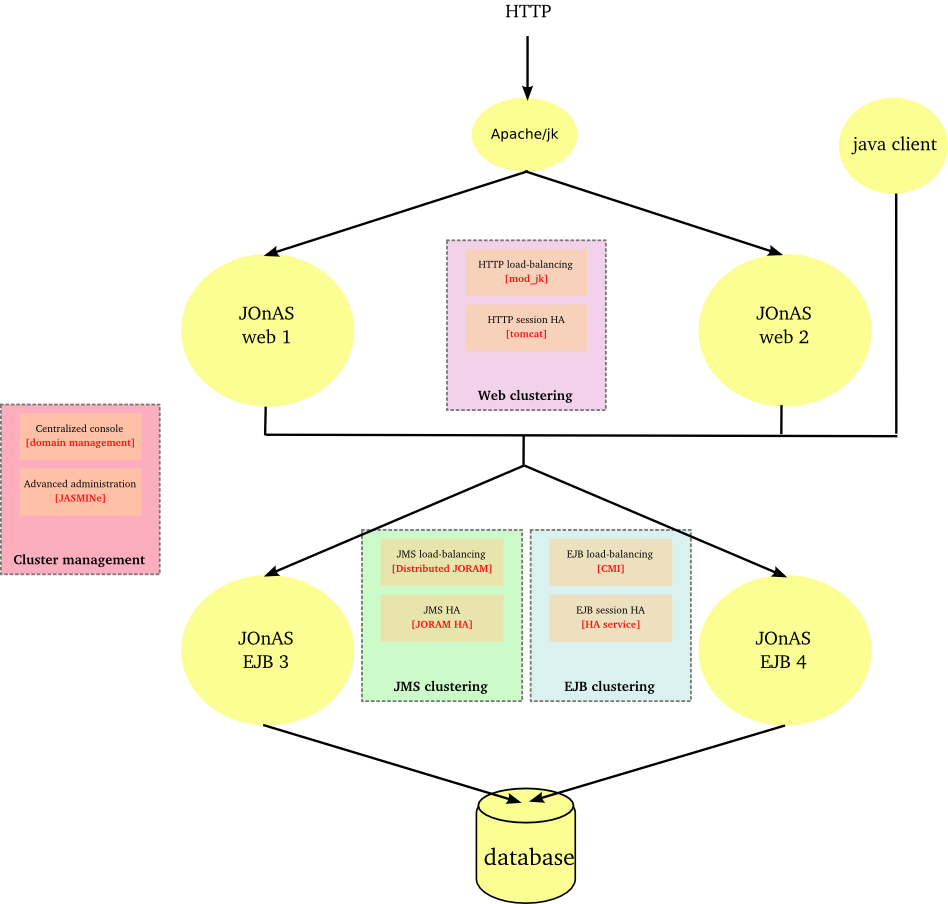
JOnAS provides an end to end solution for clustering that ensures transparent distribution, high availability and scalability of Java EE applications.
-
At the web level through
Apache/mod_jk or Apache/mod_proxy_balancer for load-balancing the HTTP flow between multiple JOnAS/Tomcat instances.
Tomcat for providing a TCP-based solution of HTTP session replication, ensuring their high availability
At the JNDI level through CMI and its replicated registry
At the EJB level (EJB2 and EJB3 support) through CMI and its cluster proxy
At the JMS level through JORAM server and JORAM HA
At the management level through the domain management feature and the JASMINe project.
 |
A farm is a set of similar JOnAS nodes gathered for ensuring scalability and a first level of availability.
A cluster is a set of similar JOnAS nodes gathered for ensuring high availablity.
![[Note]](../../resources/images/note.png) |
Note |
|---|---|
|
note: the |
A replication domain is a subset of a JOnAS cluster which determines the replication boundaries.
The concept ensures the scalability of the replication when dealing with a large number of nodes.
A JOnAS node or JOnAS instance is an autonomous server with its
own configuration and running in a dedicated JVM. Several JOnAS nodes may lie in the same
virtual or real system.
A JOnAS domain gathers a set of JOnAS nodes under the same administration authority.
A domain is defined by a name and the JOnAS nodes belonging to a domain must have an unique name within this domain.
A master node is a JOnAS node of a domain dedicated to the administration. It enables to
manage the JOnAS instances of a domain from a centralized point. Several master nodes can be defined within a domain.
The scalability of a system lies in its capacity to evolve in power by adding or removing software and hardware elements without impact on its architecture.
The scalability aims at adjusting the system bandwidth to fit with the performance needs of the service. It is achieved by replicating the resources within a farm according to the input requests load.
Farming provides a first level of availability: when a resource failure occurs, the request will be submitted again (fail-over mechanism) and will be routed towards another resource. In this case, the failure is not transparent to the user whose request is processed by the failed resource. But the service is not interrupted as the user can restart its operation. For the users whose requests are processed by other resources within the farm, the failure will be transparent and the only impact will be the response time due to load distributing among a smaller number of resources.
The high availability of a system lies in its capacity to serve requests under heavy load and despite any component failure.
A highly available architecture contains some replicated elements. The number of replicas determines the number of simultaneous failures the system is able to tolerate without interruption of service. According to the fail over implementation, the service may be damaged during a short period. This service malfunction may impact users at different levels.
Replication mechanisms contribute to the continuity of service and enable to mask the resources failures to the users (or at least to minimize their visibility). Such mechanisms do impact the system sizing as they consume more resources or for a same sizing do impact the global performance.
Ensuring the scalability of a web application
Improving the availability of a web application (without session replication)
HTTP farming consists in distributing the processing load across N JOnAS instances. The same application is deployed all over the cluster and a request may be processed by any instance.
A load-balancer is setup in front of the JOnAS instances. The intermediate device handles the site url in order to mask the JOnAS instances multiplicity to the users. The load-balancer supports the HTTP session affinity in order to route a client towards the server hosting its session.
A load-balancer may be a software or a hardware device or a mix of two. The application server instances may be collocated on a same machine or may be distributed across several machines.
The intermediate device may be duplicated for avoiding a SPOF.
Hereinafter the figure illustrates a HTTP farm composed of a L4 switch, 2 Apache servers and N JOnAS instances.
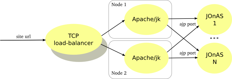 |
The Apache server is configured with the mod_jk plugin for ensuring the load-balancing between the JOnAS instances and the session affinity through the AJP protocol. Furthermore mod_jk supports the failover when a server crashes. The Apache server may be used for caching the static pages, performing compression or encryption and, thus, can reduce the application servers load.
|
Note |
|---|---|
|
From Apache 2.2, mod_proxy_balancer is alternative to the mod_jk plugin. It supports AJP protocol but also HTTP and FTP. |
The number of JOnAS instances must be determined according to the expected performance. The Apache server being a SPOF, it should be duplicated and a network device distributes the load at the TCP level between them. Of course the network device should be replicated as well (primary/backup mode).
HTTP farming is very common and widespread. It fits well with the more frequent requirements in terms of scalability and availability. Furthermore, this architecture pattern can be used for implementing a cluster of web service providing that the web service is standard and is stateless.
When the application server tier gets a bottleneck, this architecture enables to improve the performance by adding some JOnAS instances.
The application server may be unstable, in particular under heavy load. This architecture enables to improve the availability by reducing the impact of failures. However the failures are not transparent to the users who are connected to the in-fault server since they lose theirs sessions. To be note that after a crash, the load is distributed between the survivors servers what may impact the performance.
HTTP clustering is used when service continuity of web application is expected and when failures must be transparent for the users. It consists in replicating the HTTP sessions on P JOnAS instances among N.
The session context is replicated across a replication domain. Domain members are met through a multicast based protocol. The session replication takes place through point to point protocol (TCP based) and the replication mode can be synchronous (the user response is sent after the replication) or asynchronous (the user response is immediate and the replication is delayed).
Hereinafter the figure illustrates cluster with 4 JOnAS instances behind an Apache server. Requests are load-balanced across the 4 instances . The jk connector handles the session affinity and ensures that all the requests related to one session are routed towards the same instance. 2 replication domain are defined and each session is replicated on 2 JOnAS instances hosting by 2 different nodes for ensuring not to lose a session when a crash node occurs.
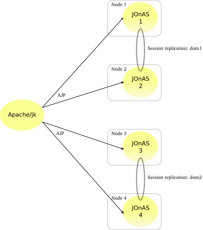 |
The Apache server can be duplicated for avoiding a SPOF.
Such a configuration lies both in the Apache/jk elements (related to the load-balancing) and in the JOnAS instances (related to the session replication).
At the jk level, a load-balancer worker is defined with 4 AJP workers. Session affinity is set and two domains are configured.
At the JOnAS level, the
tomcat6-server.xmlfile defines an AJP connector, a jvmRoute attribute set to a hosting domain and a cluster element for the replication. To be noted that the web application meta-data must be defined as distributable through thedistributableelement.
|
Note |
|---|---|
|
From Apache 2.2, mod_proxy_balancer is alternative to the mod_jk plugin. It supports AJP protocol but also HTTP and FTP. |
HTTP clustering must be used only when the HTTP session loss is not acceptable. A server failure is visible only for the connected users who have an on-going request processed by the failed instance. The fault will be transient, the request will be sent towards another server which hosts a backup of the session.
The HTTP session replication impacts the performance and causes an overhead on the system resources consumption (memory. network, cpu). Moreover, the replication in a synchronous mode induces an extra latency.
For reducing the performance impact, it is recommended to use a dedicated network interface for the HTTP session replication (separated from the AJP requests) and to limitate the replication across 2 JOnAS instances (replication domain).
EJB farming aims at providing:
scalability of the EJB tier
availability of the EJB tier (without session replication)
EJB2 and EJB3 farming are supported by JOnAS.
The EJB tier duplication is not visible for the client.
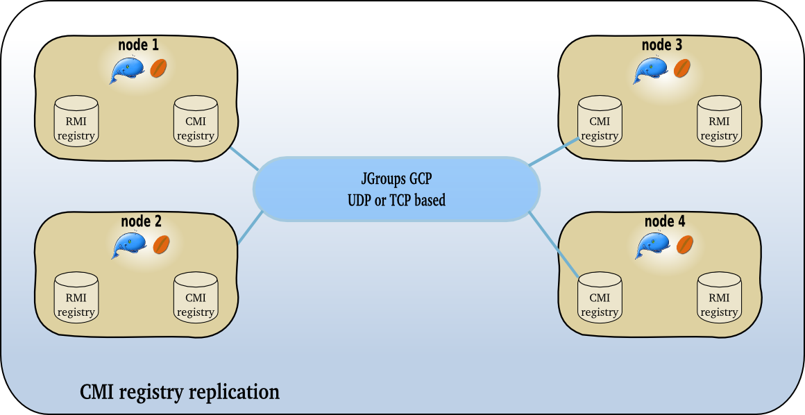
EJB farming relies on the CMI component which enables clustering on top of different RMI protocols such as jrmp, iiop or irmi.
When a client program intends to access an EJB, it invokes a JNDI registry lookup for getting an EJB home or EJB remote proxy. In an EJB farm, the CMI registry is replicated in order to provide a cluster view to the client. The cluster view represents a a list of JOnAS nodes hosting the EJB with additional clustering meta-datas. The replication and the group membership rely on the JGroups's group communication protocol. The cluster view is updated dynamically through a control channel and a dedicated control thread in the client JVM. The CMI client proxy ensures the load-balancing and the fail-over of the EJB invocations.
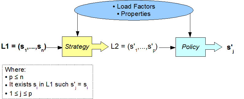
In the clustering meta-datas, the cluster logic defines both the load-balancing and fail-over algorithms. The cluster logic can be customized. A set of default policies are provided with CMI: round-robin, first available, random, etc... For each one, a strategy can be added, for example, local preference (for dealing with the collocated mode) or weighted round-robin (for adding a weighting).
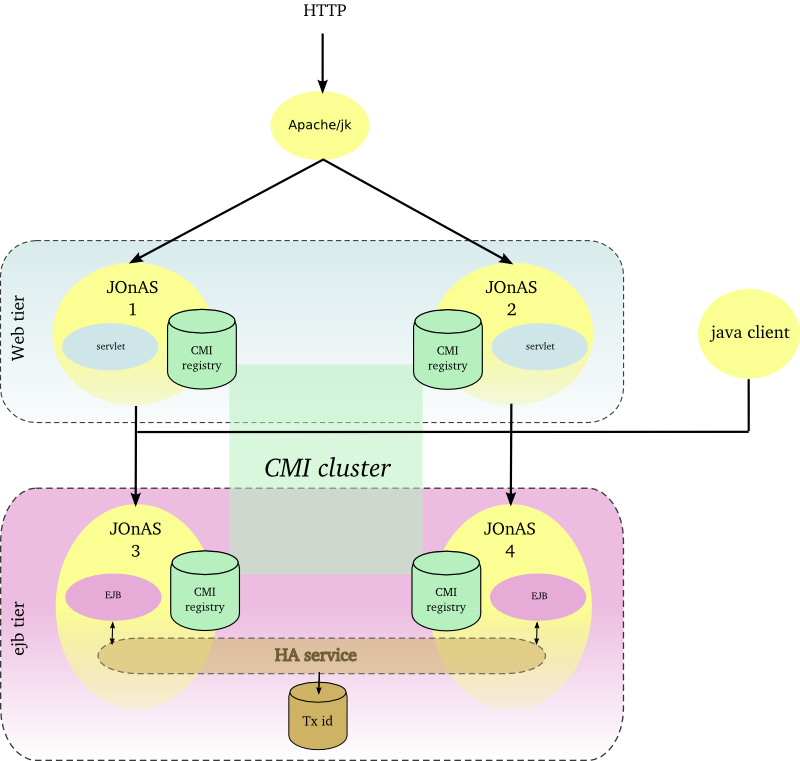
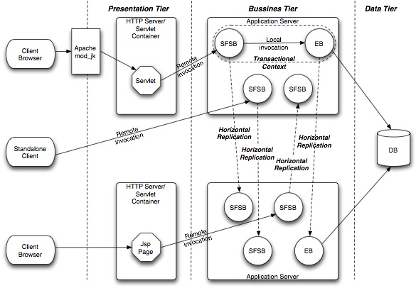
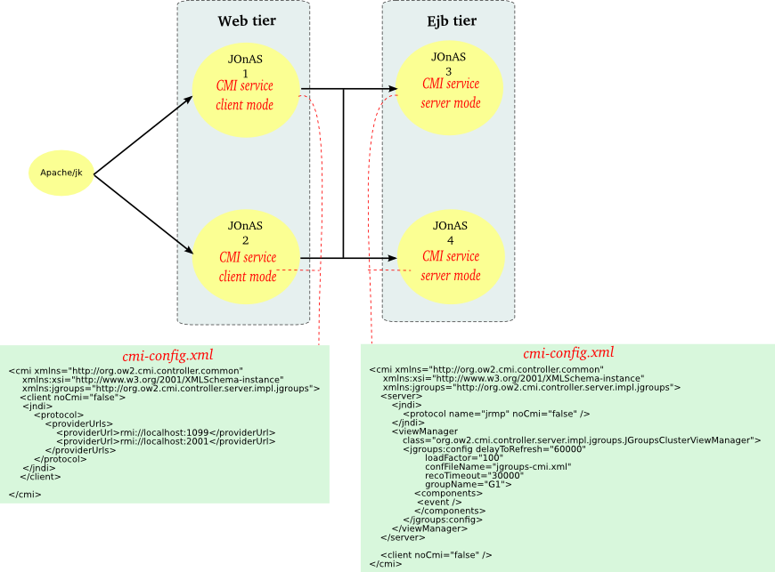
Hereinafter the figure illustrates a EJB farm in a 2 tier architecture with both web client and java client.
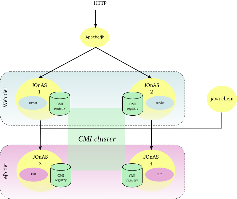 |
The Apache server is configured with the mod_jk plugin for ensuring the load-balancing between the JOnAS instances and the session affinity. Two JOnAS instances (1-2) host the presentation layer and are configured with a servlet container. Two JOnAS instances (3-4) host the business layer and are configured with an ejb container. The CMI registry is replicated across the cluster members in order to share informations about EJBs deployment and topology. Both servlet and java clients do access to EJB and do benefit from load-balancing and availability. In the case of a SFSB (stateful session bean), the EJB is created only in one instance and the state is lost if the JOnAS instance crashes, state replication is addressed in Section 2.2.8, “EJB cluster”.
The JOnAS instances number must be determined according to the expected performance.
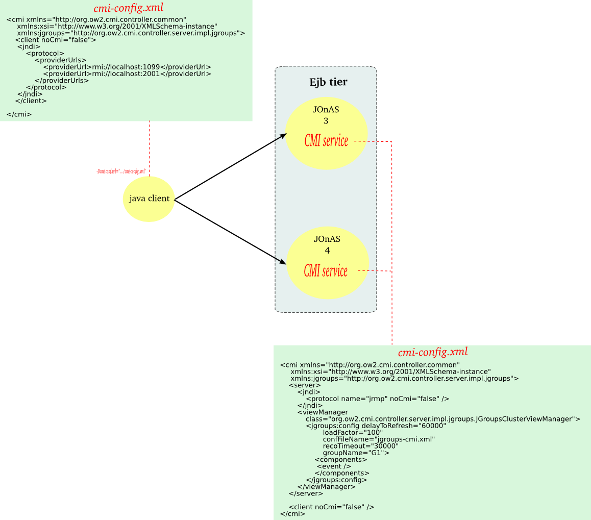
EJB distribution aims at deploy a JavaEE application which is distributed on many JOnAS instances.
EJB distribution also relies on the CMI component.
Without CMI, EJB needs to be modified to allow invocations on the remote EJBs, for example by setting the Context.PROVIDER_URL of the remote registries or by using the specific features of the IIOP protocol. With CMI, EJB can continue to access to the remote EJBs as if they were locally deployed.
EJB clustering is used when service continuity of ejb application is required and when any failure must be transparent for the users. It relies on the stateful EJB replication and manages the transaction in order to:
ensure that the replicated system do have a similar behavior of the not replicated one,
in case the client doesn't abort, the transaction is executed exactly once, and no more than once otherwise.
The EJB replication relies on
-
a mechanism for replicating the state of the EJBs and the business methods invocation return values. This mechanism is provided by the HA service and different implementations do exist (JGroups) or are under development (Terracotta, Pair replication);
a mechanism for marking the transaction in a persistent database. The information is used at the fail-over time to determine whether the transaction was aborted and whether the request must be replayed.
a smart proxy in charge of redirecting the client calls towards another replica when a failure occurs.
An EJB is replicated only if it is specified as replicated in the component meta-datas (annotation and/or deployment descriptor).
A stateful ejb is created on a JOnAS instance selected according to a load-balancing algorithm (default is round-robin). After the creation all the business methods invocations are routed to this JOnAS instance unless a failure occurs.
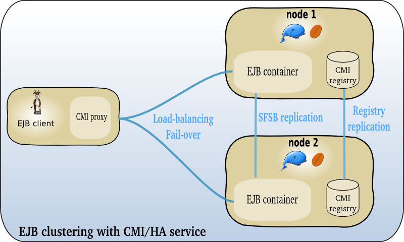
Hereinafter the figure illustrates a EJB cluster.
 |
Each JOnAS instance of the EJB tier is configured with the HA service in charge of the session replication. CMI client API supports fail-over for both EJB2 and EJB3.
This architecture pattern is recommended when the application contains some stateful EJB and doesn't tolerate any session loss and any interruption of service. However the user must be aware that this kind of setting does impact highly the performance as the session is replicated between the JOnAS server at each method call.
JMS Farming aims at:
ensuring the scalability of asynchonous applications,
improving the availability of asynchonous applications.
JMS farming consists in distributing the messages load across N JOnAS instances. The same application is deployed all over the cluster and a message may be processed by any instances.
JMS farming relies on the distribution capabilities of the JORAM product. Load-balancing can take place both at the server side or at the client side. When a server crashes, pending messages are lost unless a specific mechanism is set up at the disk level (such mechanisms are addressed in Section 2.2.10, “JMS cluster”).
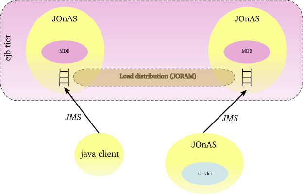
At the server side, messages can be redirected towards other JOnAS instances when the load reaches a threshold.
Hereinafter the figure illustrates a JMS farming with a distribution control at the server side.
 |
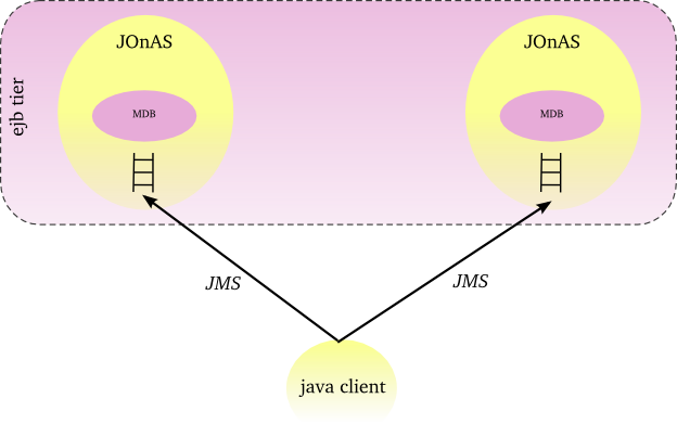
At the client side, messages can be distributed across a set of JOnAS instances according to a load-balancing algorithm (default is random).
Hereinafter the figure illustrates a JMS farming with a distribution control at the client side.
 |
JMS farming fits well with the need of scalability and availability of the EDA (Event Driven Architecture) applications. When the application provides a JMS based asynchronous interface, the JORAM's clustering capabilities do enable to equilibrate the load either from the client side or from the server side. JMS farming is recommended when the message loss is acceptable and constitutes a good compromise in terms of performance and flexibility.
JMS cluster is used when the messages loss is not acceptable and when the interruption of service is not permitted.
Two solutions are available for ensuring the messaging high availability with JOnAS:
-
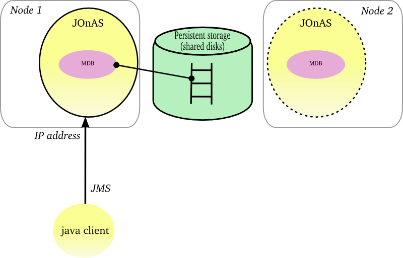
through the persistent mode of JORAM combined with some cluster features at the operating system level (NFS, HA/CMP product, Veritas product, ...). The HA OS must provide a HA network address (virtual ip address) which can be reallocated dynamically when a node failure occurs. JMS objects, topics and queues, must be stored on a shared disk space (external disk array or shared disk space as NFS). JORAM supports 2 storage types : file and database. When a JOnAS instance fails, the on-going messages are retrieved by a backup instance in the persistent storage, the virtual IP address is bound to the backup node and the messages are processed.
-
through JORAM HA concept delivered with the JORAM project. The mechanism relies on a Master/Slaves approach. At one point, only the master instance is active and all the JMS requests are replicated towards the slaves instances. The JMS replication is synchronous and implemented with JGroups.
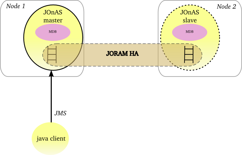
This architecture pattern is recommended when the application doesn't tolerate any message loss and any interruption of service. Two mechanisms are available: the first one relies on operating system HA features and the JORAM's persistent mode whereas the second one relies on the native JORAM capabilities and a replication of the JMS requests. In case of the underlying OS provides HA features, the first solution is simpler in term of configuration and provides better performance. Otherwise JORAM HA solution can be considered and the user must pay attention to the performance impact.
Each JOnAS instance can be managed through a local jonasAdmin console. The domain management enables to manage a set of JOnAS instances from a centralized jonasAdmin console.
A domain is a set of JOnAS instances that are running under the same management authority. The instances within a domain can be standalone, distributed or gathered in a cluster as well. The instances are managed from an unique console deployed in a dedicated JOnAS instance named master, configured with the domain management enabled.
Domain management is composed of the following features:
- discovery service for detecting automatically the instances and the clusters.
- JOnAS instance and cluster monitoring for maintaining a JOnAS instance state view and a cluster view as well as for tracking some indicators.
- JOnAS instance control for remote starting or remote stopping of the JOnAS instances.
- domain-wide deployment for deploying Java EE modules across a set of JOnAS instances or clusters.
- instance configuration for setting or retrieving a configuration attribute from a JOnAS instance as available through a local jonasAdmin console.
Several interfaces are provided:
- console with the centralized jonasAdmin console.
- command with the jonas admin command which has been extended to deal with domain.
- JMX through some domain management MBeans.
The domain management is optional. When enabled, JOnAS instance within a domain must have an uniq name instance.
The domain management relies on:
- MBeans objects deployed in each JOnAS instance and accessible through the JMX remote interface.
- One or several management JOnAS instances masters hosting the domain management features.
- Optionaly some cluster daemons enabling to control remotely the JOnAS instances.
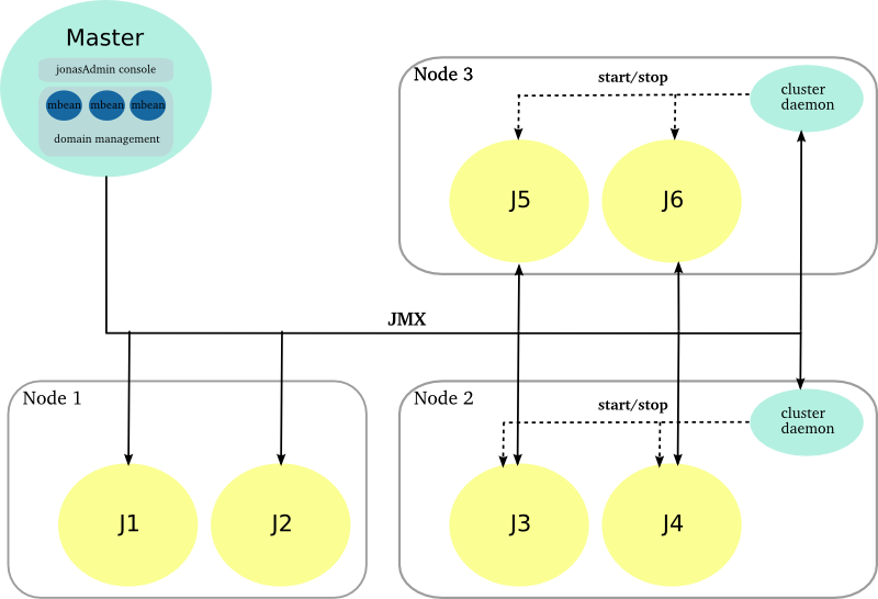 |
A dedicated JOnAS is assigned with the master role which enables the domain management feature. The jonasAdmin console is deployed in this instance and is no more necessary in the others ones.
The domain management functions are exposed through a set of MBeans that are used by the jonasAdmin console.
The master instance interacts with the managed JOnAS instances and the cluster daemons through JMX. The master node periodically polls the managed instances for providing states and statistics.
Several master instances can be defined for high availability, only one must be enabled at one point.
The cluster daemon is in charge of controlling the JOnAS instances (start/stop) that are collocated on the same machine. It is an optional component in the domain management infrastructure and can be added on an existing configuration.
It is accessible through a JMX Remote interface and provides the start/stop operations. By default, it relies on the native JOnAS command for driving the JOnAS instances. The user may put its own commands for setting a particular environment before starting/stopping a JOnAS node.
The managed JOnAS instances must respect some conventions for domain management:
- the managed instance must be aware of the domain.
- the managed instance must have an unique name in the domain.
Both domain name and instance name are specified in the starting command:
jonas start -n instance_name -Ddomain.name=domain_name.
The discovery service aims at detecting when a new JOnAS instance appears or when a JOnAS instance leaves the domain. It enables the master instance to retrieve the managed instances without any prior informations about them.
Two implementations of the discovery service are available (the choice is done by configuration):
- a IP multicast based implementation.
- a JGroups based implementation. The group communication protocol stack can be configured on top of UDP or TCP.
The first one relies on IP multicast whereas the second one uses point to point communication.
If the managed instances cannot be discovered automatically due to the network configuration or the administration policies, the domain topology can be described statically in the domain.xml file.
JOnAS provides different administration interfaces:
- a graphical console with jonasAdmin console that can be centralized if deployed in the master instance.
- a
jonas admincommand has been extended for supporting the domain management feature (remote control, cluster-wide deployment and so on. - a JMX interface through the JOnAS MBeans.
- a EJB interface through the mejb.
- a Web Service interface through the mejb.
For the management point of view, a cluster is a group of JOnAS instances. The JOnAS instances within a cluster are called cluster members. A JOnAS instance may be a member of several clusters in the domain.
A cluster is an administration target in the domain: from the common administration point of view, the administrator may monitor the cluster or apply to it management operations like deploy or undeploy of applications.
There are two main cluster categories:
-
Clusters containing instances that are grouped together only to facilitate management tasks.
-
Clusters containing instances that are grouped together to achieve objectives like scalability, high availability or failover.
The clusters in the first category, called Logical Cluster, are created by the domain administrator based on his/her particular needs. The grouping of servers (the cluster creation) can be done even though the servers are running.
In the second case, the servers which compose a cluster must have a particular configuration that allows them to achieve the expected objectives. Once servers are started, the management domain feature is able to automatically detect that they are cluster instances, based on configuration criteria and MBeans discovery. Several cluster types are supported by the domain management function. They correspond to the different roles a cluster can play:
-
JkCluster - allow HTTP request load balancing and failover based on the mod_jk Apache connector.
-
TomcatCluster - allow high availability at web level based on the Tomcat HTTP session replication solution.
-
CmiCluster - enable JNDI clustering and allows load balancing at EJB level, based on the CMI protocol
-
JoramCluster - allow JMS destinations scalability based on the JORAM distributed solution.
-
JoramHa - allow JMS destinations high availability based on JORAM HA.
Advanced administration features are provided through the JASMINe project:
- JASMINe Design for building a cluster configuration through a graphical interface.
- JASMINe Deploy both for deploying the middleware and the applications across a distributed infrastructure.
- JASMINe Monitoring for helping the operator to detect errors and for tracking the performance.
- JASMINe SelfManagement for improving the system reliability and performance automatically.
As with other Apache modules, mod_jk should be first
installed on the modules directory of the Apache Web
Server and the
httpd.conf
file has to be updated. Moreover, mod_jk requires
workers.properties
file that describes the host(s) and port(s) used by the
workers.
Here we provide an example of
workers.properties
file to connect the Apache frontal with two
workers. The file defines a
load-balancing
worker named
myloadbalancer
, and the two
balanced
workers,
worker1
and
worker2
. Each cluster member will be configured to play the
role of one of the balanced workers. Additionally, a
status worker jkstatus is defined for controlling
and monitoring the load-balancing.
Example 3.1. Configuring mod_jk workers
#-----------------------
# List the workers name
#-----------------------
worker.list=myloadbalancer,jkstatus

#-----------------------
# worker1
#-----------------------
worker.worker1.port=9010
worker.worker1.host=localhost
worker.worker1.type=ajp13 # Load balance factor
worker.worker1.lbfactor=1 # Define preferred failover node for worker1
#worker.worker1.redirect=worker2 # Disable worker1 for all requests except failover
#worker.worker1.disabled=True
#-----------------------
# worker2
#-----------------------
worker.worker2.port=9011
worker.worker2.host=localhost
worker.worker2.type=ajp13 # Load balance factor
worker.worker2.lbfactor=1 # Define preferred failover node for worker2
#worker.worker2.redirect=worker2 # Disable worker2 for all requests except failover
#worker.worker2.disabled=True
#-----------------------
# Load Balancer worker
#-----------------------
worker.myloadbalancer.type=lb
worker.myloadbalancer.balance_workers=worker1,worker2
worker.myloadbalancer.sticky_session=false
#-----------------------
# jkstatus worker
#-----------------------
worker.jkstatus.type=status
For a complete documentation about
workers.properties
see the Apache Tomcat Connector
guide
.
The Apache configuration must be enhanced for loading the mod_jk plugin with its setting. The following lines
have to be added to the httpd.conf file directly or included from another file:
Example 3.2. Configuring mod_jk mount points
# Load mod_jk module
# Update this path to match your modules location
LoadModule jk_module modules/mod_jk.so
# Location of the workers.properties file
# Update this path to match your conf directory location JkWorkersFile
# (put workers.properties next to httpd.conf)
/etc/httpd/conf/workers.properties
# Location of the log file JkLogFile /var/log/mod_jk.log
# Log level : debug, info, error or emerg
JkLogLevel info
# Select the timestamp log format
JkLogStampFormat "[%a %b %d %H:%M:%S %Y] "
# Shared Memory Filename ( Only for Unix platform ) required by loadbalancer
JkShmFile /var/log/jk.shm
# Assign specific URL to the workers
JkMount /sampleCluster2 myloadbalancer
JkMount /sampleCluster2/* myloadbalancer
JkMount /sampleCluster3 myloadbalancer
JkMount /sampleCluster3/* myloadbalancer
# A mount point to the status worker
JkMount /jkmanager jkstatus
JkMount /jkmanager/* jkstatus

# Copy mount points into all virtual hosts
JkMountCopy All

# Enable the Jk manager access only from localhost
<Location /jkmanager/>
   JkMount jkstatus
   Order deny,allow
   Deny from all
   Allow from 127.0.0.1
</Location>
The location of the workers.properties file has to be adapted to your environment.
The JkMount directives specify the routes that are managed by mod_jk. The examples of
context urls pattern have to be replaced with your application ones.
For a complete documentation see Apache
HowTo
.
Each cluster member needs an AJP/1.3 connector listening on the
port defined in the workers.properties file. Moreover,
the worker name (here in the example, worker1/worker2) must be used as
value for the Engine's
jvmRoute
attribute.
Here is a chunk of tomcat6-server.xml configurations file for
the member worker1:
Example 3.3. Configuring an AJP connector in Tomcat
<Server>
  <!-- Define the Tomcat Stand-Alone Service -->
  <Service name="Tomcat-JOnAS">
    <!-- Define a non-SSL Coyote HTTP/1.1 Connector on port 9000 -->
    <Connector port="9000" protocol="HTTP/1.1" connectionTimeout="20000"
        redirectPort="9043" />
    <!-- AJP 1.3 Connector on port 9010 for worker.worker1.port in workers.properties file -->
    <Connector port="9010" redirectPort="9043" protocol="AJP/1.3"/>

    <!-- An Engine represents the entry point You should set jvmRoute to support load-balancing via AJP ie : -->
    <Engine name="jonas" defaultHost="localhost" jvmRoute="worker1">
    </Engine>
  </Service>
<Server>
Contrary to mod_jk, mod_proxy_balancer supports HTTP and AJP protocols. Thus the cluster member can
specify either an AJP/1.3 connector or a HTTP connector. In both case, the connector port number must be the same than the port number
defined in the Apache's configuration file.
Moreover, the BalancerMember route parameter must be used as value for the Engine's
jvmRoute
attribute.
The load-balancing is configured as a WEB farm, see Section 3.1.1, “Configuring a WEB farm with mod_jk” and Section 3.1.2, “Configuring a WEB farm with mod_proxy_balancer”.
Additionally to HTTP requests load balancing provided by mod_jk, transparent failover for Web applications can be reached by using HTTP session replication provided by the Tomcat clustering solution.
Web cluster members are JOnAS instances having the web container service activated, using the Tomcat implementation, and having a specific configuration which allows them to be members of a Tomcat cluster.
The concerned configuration file is the
tomcat6-server.xml
file. Every member of the cluster must have a Cluster
element defined in the default virtual host definition.
The cluster name is defined by the clusterName
attribute, which should be the same for all the cluster
members. Another common element for the cluster members
is the Membership definition.
The example below defines a configuration of the Cluster element for an all-to-all session replication with the DeltaManager.
This works great for small cluster. For larger cluster, BackupManager enables to replicate the session data to one backup node,
and only to nodes that have the application deployed. See the
documentation
for more informations.
Example 3.4. Configuring the HTTP session replication in Tomcat
      <!-- Define a Cluster element -->
      <Cluster className="org.apache.catalina.ha.tcp.SimpleTcpCluster"
                 channelSendOptions="8" clustername="mycluster" >
          <Manager className="org.apache.catalina.ha.session.DeltaManager"
                   expireSessionsOnShutdown="false"
                   notifyListenersOnReplication="true"/>
          <Channel className="org.apache.catalina.tribes.group.GroupChannel">
            <Membership className="org.apache.catalina.tribes.membership.McastService"
                        address="228.0.0.4"
                        port="45564"
                        frequency="500"
                        dropTime="3000"/>
            <Receiver className="org.apache.catalina.tribes.transport.nio.NioReceiver"
                      address="auto"
                      port="4000"
                      autoBind="100"
                      selectorTimeout="5000"
                      maxThreads="6"/>
            <Sender className="org.apache.catalina.tribes.transport.ReplicationTransmitter">
              <Transport className="org.apache.catalina.tribes.transport.nio.PooledParallelSender"/>
            </Sender>
            <Interceptor className="org.apache.catalina.tribes.group.interceptors.TcpFailureDetector"/>
            <Interceptor className="org.apache.catalina.tribes.group.interceptors.MessageDispatch15Interceptor"/>
          </Channel>
          <Valve className="org.apache.catalina.ha.tcp.ReplicationValve"
                 filter=""/>
          <Valve className="org.apache.catalina.ha.session.JvmRouteBinderValve"/>
          <ClusterListener className="org.apache.catalina.ha.session.JvmRouteSessionIDBinderListener"/>
          <ClusterListener className="org.apache.catalina.ha.session.ClusterSessionListener"/>
        </Cluster>
|
Note |
|---|---|
|
the
clusterName
attribute is mandatory for administration purpose (and not set by default
in
|
CMI and HA service do provide the following clustering features:
JNDI high availability through the registry replication and the multi-target lookup
-
EJB load-balancing and fail-over through the CMI cluster proxy
for the EJB2.1 home interface (SSB, SFSB, EB)
for the EJB2.1 remote interface (SSB)
for the EJB3 (SSB, SFSB)
-
EJB high availability with the HA service
for the EJB2.1 SFSB
EJB3 support being under development
 |
CMI is an OW2 project providing a framework to define and configure clusters of RMI objects. CMI is embedded both in JOnAS and EasyBeans projects.
The main features are :
Support of EJB2 and EJB3
Definition of the cluster logic with simple POJO (policy and strategy)
Delivery of a set of predefined policies (round robin, first available, random, ...) and strategies (weighted, local preference, ...)
Dynamic update of the policy and strategy from the server side
Smooth shutdown of a cluster member
JMX management
Separation of the control flow and the service flow
multi-protocols support: jrmp, irmi, iiop
|
Note |
|---|---|
|
CMI described in this section is CMI v2 available in JOnAS 5 (not in JOnAS 4). |
The following figure shows how to define a weighted round-robin in term of policy and strategy.
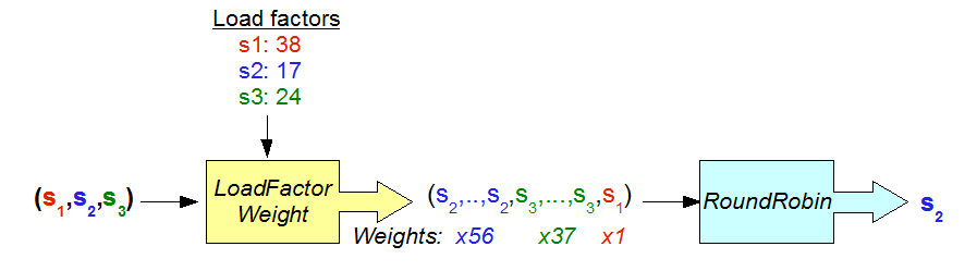 |
An use of the weighted round-robin
HA service provides High Availability for the EJB. A first implementation based on the Horizontal replication is delivered for EJB2.1. Other solutions are under development: Terracotta based and pair replication.
Stateful session beans (EJB2.1) can be replicated since JOnAS 4.7 in order to provide high availability in the case of failures in clustered environments. A new service called High Availability (HA) has been included in JOnAS to provide replication mechanisms. JOnAS HA also requires the cluster method invocation (CMI) protocol.
From JOnAS 4.8, a new replication algorithm based on a horizontal replication approach is available. The algorithm improves the algorithm implemented for JOnAS 4.7 with the following enhancements:
Replication of SFSBs with references to EBs: The algorithm can replicate SFSBs that reference EB by means of both, local or remote interfaces.
Transaction awareness: The algorithm is transaction aware, meaning that the state is not replicated if the transaction aborts.
Exactly-once semantics: Each transaction is committed exactly once at the DB if the client does not fail. If the client fails, each transaction is committed at most once at the DB
JOnAS implements an update-everywhere replication protocol according to the database replication terminology (See the J. Gray et al.'s paper ''The dangers of replication and a solution'' in proceedings of the ACM SIGMOD 96's conference, Canada). In this protocol, a client can connect to any server. When the client calls the create() method on the SFSB's Home interface, the server the client connects to is selected following a round-robin scheme. All the requests from the client to the SFSB will be processed by this server until the client calls the remove() method on the remote interface. The rest of the servers will act as backups for that client. Before sending the response to the client, the SFSB's state is sent to the backups.
If the server fails, another server among the backups will be selected to serve the client requests, first restoring the current state of the SFSBs from the state information stored in the HA local service. From this point on, this server will receive the new client requests.
The supported replication scenarios are shown in the following figure:
 |
The horizontal approach aims to guarantee that the transactions are kept consistent when a fail-over occurs. They are either aborted or restored for ensuring the exactly-once semantics. During a fail-over, the new primary uses a special table in the database for storing the transaction identifier and enabling to find out if the transaction was committed or not.
If the transaction is aborted due to the primary failure, then the new primary will not find the transaction identifier in the special table. The request will be replayed.
If the transaction is committed, then the new primary will find the transaction identifier, which means that the transaction was committed. The request won't be replayed; the replicated result is returned.
Beyond the SFSB replication, the algorithm enables the building of applications (stateful or stateless) with a high level of reliability and integrity.
The setting of an EJB farm is achieved by
- configuring the CMI service
- configuring the registry distribution
- configuring the EJB application
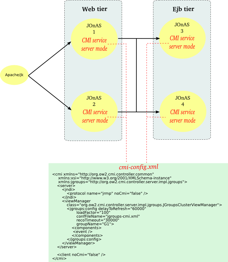
The configuration of the cmi service
is available through the file
$JONAS_BASE/conf/cmi-config.xml.
The CMI service can be configured in two modes:
-
server mode with a cluster view manager created locally, i.e. with a local instance of a replicated CMI registry.
-
client mode without a local cluster view manager, in this case a list of providers urls (i.e. a list of cluster view manager urls) is given for accessing to the remote CMI registries.
The server mode is simpler to configure, the client mode requires to define statically a list of providers urls. The server mode starts a Group Communication Protocol instance (e.g. JGroups) and thus increases the resources consumption compare to the client mode.
|
Note |
|---|---|
|
The CMI configuration file may contain two parts: a
|
The server element contains the following elements:
Example 3.5. Configuring the cmi service in the server mode
<cmi xmlns="http://org.ow2.cmi.controller.common"
xmlns:xsi="http://www.w3.org/2001/XMLSchema-instance"
xmlns:jgroups="http://org.ow2.cmi.controller.server.impl.jgroups">
<server>
<jndi>  <protocol name="jrmp" noCmi="false" />
</jndi>
<viewManager
<protocol name="jrmp" noCmi="false" />
</jndi>
<viewManager  class="org.ow2.cmi.controller.server.impl.jgroups.JGroupsClusterViewManager">
  <jgroups:config
  delayToRefresh="60000"
  loadFactor="100"
  confFileName="jgroups-cmi.xml"
  recoTimeout="30000"
  groupName="G1">
  <components>
  <event />
</components>
</jgroups:config>
</viewManager>
</server>
</cmi>
<event />
</components>
</jgroups:config>
</viewManager>
</server>
</cmi>
|
|
|
|
|
|
|
|
|
|
|
|
|
|
|
|
|
|
|
|
|
Note |
|---|---|
|
Refer to the clustering guide for issues related to JGroups. |
The client element contains the following elements:
Example 3.6. Configuring the cmi service in the client mode
<cmi xmlns="http://org.ow2.cmi.controller.common"
     xmlns:xsi="http://www.w3.org/2001/XMLSchema-instance">

    <client noCmi="false">
    	<jndi>
        	<protocol name="jrmp">
            	<providerUrls>
                	<providerUrl>rmi://localhost:1099</providerUrl>
                	<providerUrl>rmi://localhost:2001</providerUrl>
            	</providerUrls>
        	</protocol>
    	</jndi>
    </client>
</cmi>
|
|
|
|
By default, CMI relies on JGroups group-communication protocol for ensuring the global registry distribution. The parameters are gathered in the:
$JONAS_BASE/conf/cmi-config.xml for specifying the JGroups configuration file name and the JGroups group name.
$JONAS_BASE/conf/jgroups-cmi.xml file for the settings of the jgroups protocol stack. By default, the JGroups configuration uses the UDP protocol and the multicast IP for broadcasting the registry updates. A TCP-based stack can be used in a network environment that does not allow the use of multicast IP or when a cluster is distributed over a WAN.
 |
For example, the jgroups-cmi.xml file may contain the following stack configuration:
Example 3.7. JGroups's configuration stack
<config>
    <UDP mcast_addr="224.0.0.35"
         mcast_port="35467"
         tos="8"
         ucast_recv_buf_size="20000000"
         ucast_send_buf_size="640000"
         mcast_recv_buf_size="25000000"
         mcast_send_buf_size="640000"
         loopback="false"
         discard_incompatible_packets="true"
         max_bundle_size="64000"
         max_bundle_timeout="30"
         use_incoming_packet_handler="true"
         ip_ttl="2"
         enable_bundling="true"
         enable_diagnostics="true"
         thread_naming_pattern="cl"

         use_concurrent_stack="true"

         thread_pool.enabled="true"
         thread_pool.min_threads="1"
         thread_pool.max_threads="25"
         thread_pool.keep_alive_time="5000"
         thread_pool.queue_enabled="false"
         thread_pool.queue_max_size="100"
         thread_pool.rejection_policy="Run"

         oob_thread_pool.enabled="true"
         oob_thread_pool.min_threads="1"
         oob_thread_pool.max_threads="8"
         oob_thread_pool.keep_alive_time="5000"
         oob_thread_pool.queue_enabled="false"
         oob_thread_pool.queue_max_size="100"
         oob_thread_pool.rejection_policy="Run"/>

    <PING timeout="2000"
            num_initial_members="3"/>
    <MERGE2 max_interval="30000"
            min_interval="10000"/>
    <FD_SOCK/>
    <FD timeout="2000" max_tries="3" shun="true"/>
    <VERIFY_SUSPECT timeout="1500"  />
    <BARRIER />
    <pbcast.NAKACK max_xmit_size="60000"
                   use_mcast_xmit="false" gc_lag="0"
                   retransmit_timeout="300,600,1200,2400,4800"
                   discard_delivered_msgs="true"/>
    <UNICAST timeout="300,600,1200,2400,3600"/>
    <pbcast.STABLE stability_delay="1000" desired_avg_gossip="50000"
                   max_bytes="400000"/>
    <VIEW_SYNC avg_send_interval="60000"   />
    <pbcast.GMS print_local_addr="true" join_timeout="3000"
                join_retry_timeout="2000" shun="true" />
    <SEQUENCER/>
    <FC max_credits="20000000"
                    min_threshold="0.10"/>
    <!--pbcast.STREAMING_STATE_TRANSFER use_reading_thread="true"/-->
    <pbcast.STATE_TRANSFER  />
    <!-- pbcast.FLUSH  /-->
</config>
|
Note |
|---|---|
| You can find more information about JGroups and about the stack configuration here. |
All the members of a cluster share the same JGroups configuration.
If several cluster partitions are required over a single LAN, several JGroups configurations must be configured with different values for the following parameters:
JGroups group name
JGroups multicast address
JGroups multicast port
When a new node appears in the cluster, its registry content is synchronized automatically.
When a node disappears, JGroups notifies the other's member of the node leaving and the registry entries related to this node are removed.
Informations must be put in the EJB meta-datas for clustering them. The following section gives a description of the clustering parameters of the EJBs and indicates how to configure the load-balancing algorithm. Afterwards, the different settings for EJB2 and EJB3 (specific deployment descriptor and/or annotation) are described.
EJB meta-data for clustering contains the following parameters:
| Parameter | Description |
| name | specifies the cluster name associated with the EJB. This information is set for administration
purpose. Default name is defaultCluster. |
| pool | describes the stubs pool configuration at the client side (one pool per EJB).
|
| policy | specifies the load-balancing algorithm policy (POJO) used for the EJB. Built-in policies are provided. The user can provide its own implementation. |
| strategy | specifies the load-balancing algorithm strategy (POJO) used for the EJB. Built-in strategies are provided. The user can provide its own implementation. |
| properties | Set of properties that may be passed to the policy and/or strategy. The parameter is optional and is reserved for an advanced use. The parameter is not used by the built-in policies and strategies and may be read by the user policies and/or strategies. |
| replicated | boolean indicating whether the ejb is replicated or not. Not applicable in farming. |
The following policies implementations are provided with JOnAS:
| Policy | Description |
| RoundRobin.class | round-robin algorithm, all the node are served sequentially. |
| Random.class | random algorithm, a node is chosen randomly. |
| FirstAvailable.class | first-available algorithm, at first a server is selected randomly and then is bound. |
| HASingleton.class | HA-singleton algorithm, all the clients are bound to the same server. |
The policies can be pointed out with some strategies:
| Strategy | Description | Applicable to policy |
| NoStrategy.class | no strategy, set by default. | All |
| LocalPreference.class | local preference, if present, a collocated server is selected. | RoundRobin, Random, FirstAvailable |
| LoadFactorWeight.class | add a weighted load factor to the policy, for example for specifying the weighted round-robin algorithm. | RoundRobin |
| LoadFactorSort.class | add a sorted load factor to the policy, for example for specifying the sorted round-robin algorithm. | RoundRobin |
CMI permits to provide its own policy and strategy. The POJO must implement CMI interfaces and the classes must be deployed across the cluster.
The policy must implement the org.ow2.cmi.lb.policy.IPolicy interface:
package org.ow2.cmi.lb.policy;

import java.lang.reflect.Method;
import java.util.Collection;

import org.ow2.cmi.lb.LoadBalanceable;
import org.ow2.cmi.lb.NoLoadBalanceableException;
import org.ow2.cmi.lb.decision.DecisionManager;
import org.ow2.cmi.lb.strategy.IStrategy;

/**
* Interface of the policies for load-balancing.
* @param <T> The type of object that was load-balanced
* @author The new CMI team
*/
public interface IPolicy<T extends LoadBalanceable> {

    /**
     * Chooses a load-balanceable among the list of load-balanceables.
     * @param loadBalanceables a list of load-balanceables
     * @throws NoLoadBalanceableException if no server is available
     * @return the chosen load-balanceable
     */
    T choose(Collection<T> loadBalanceables) throws NoLoadBalanceableException;

    /**
     * Return a strategy to modify the behavior of this policy.
     * @return a strategy to modify the behavior of this policy
     */
    IStrategy<T> getStrategy();

    /**
     * Sets a strategy to modify the behavior of this policy.
     * @param strategy a strategy of load-balancing
     */
    void setStrategy(IStrategy<T> strategy);

    /********************** Begin of callback definitions **********************/

    /**
     * Returns a decision when an exception is thrown during an access to a registry
     * for a given load-balanceable.
     * @param loadBalanceable the load-balanceable that have caused the exception
     * @param thr the exception that is thrown
     * @return the decision when an exception is thrown during an access to a registry
     * for a given load-balanceable
     */
    DecisionManager<Void> onLookupException(T loadBalanceable, Throwable thr);

    /**
     * Returns a decision when an exception is thrown during an invocation for a given
     * load-balanceable.
     * @param method the method that was invoked
     * @param parameters the parameters of the method
     * @param loadBalanceable the load-balanceable that have caused the exception
     * @param thr the exception that is thrown
     * @return the decision when an exception is thrown during an invocation for a given
     * load-balanceable
     */
    DecisionManager<Void> onInvokeException(Method method, Object[] parameters, T loadBalanceable, Throwable thr);

    /**
     * Return a decision when a server is chosen and its delegate retrieved.
     * @param <ReturnType> the type of delegate
     * @param method the method that was invoked
     * @param parameters the parameters of the method
     * @param chosenValue the delegate of chosen server
     * @return the decision when the server is chosen and its delegate retrieved
     */
    <ReturnType> DecisionManager<ReturnType> onChoose(Method method, Object[] parameters, ReturnType chosenValue);

    /**
     * Returns a decision when the invocation of a remote method ends.
     * @param <ReturnType> the type of the returned value
     * @param method the method that was invoked
     * @param parameters the parameters of the method
     * @param loadBalanceable the load-balanceable used for the invocation
     * @param retVal the returned value
     * @return the decision when the invocation of a remote method ends
     */
    <ReturnType> DecisionManager<ReturnType> onReturn(Method method, Object[] parameters, T loadBalanceable, ReturnType retVal);

}
CMI provides the org.ow2.cmi.lb.policy.AbstractPolicy abstract class for simplifying
the policies implementation. The user class can extend it and provides, at least, an implementation of the choose
method. Example for the round-robin implementation:
Example 3.8. Round-robin policy in CMI
package org.ow2.cmi.lb.policy;

import java.util.ArrayList;
import java.util.Collection;
import java.util.List;
import java.util.Random;

import net.jcip.annotations.ThreadSafe;

import org.ow2.cmi.lb.LoadBalanceable;
import org.ow2.cmi.lb.NoLoadBalanceableException;
import org.ow2.cmi.lb.strategy.IStrategy;
import org.ow2.cmi.lb.strategy.NoStrategy;
import org.ow2.util.log.Log;
import org.ow2.util.log.LogFactory;
/**
 * The default load-balancing policy (Round Robin) that always chooses the next available load-balanceable.
 * @param <T> The type of objects that are load-balanced
 * @author The new CMI team
 */
@ThreadSafe
public final class RoundRobin<T extends LoadBalanceable> extends AbstractPolicy<T> {

    /**
     * Logger.
     */
    private static final Log LOGGER = LogFactory.getLog(RoundRobin.class);

    /**
     * Initial value of the pointer.
     */
    private static final int INITIAL_VALUE = -1;

    /**
     * The pointer to store the last ref.
     */
    private int pointer;

    /**
     * Random numbers.
     */
    private final Random rand = new Random();

    /**
     * Build the Round Robin policy.
     * Give to the pointer an initial value.
     */
    public RoundRobin() {
        pointer = INITIAL_VALUE;
    }

    /**
     * Chooses the next load-balanceable among the list of load-balanceables.
     * @param loadBalanceables the list of load-balanceables
     * @throws NoLoadBalanceableException if no server available
     * @return the chosen load-balanceable
     */
    @Override
    public synchronized T choose(final Collection<T> loadBalanceables) throws NoLoadBalanceableException{

        if (loadBalanceables == null || loadBalanceables.isEmpty()) {
            LOGGER.error("The given list is null or empty: " + loadBalanceables);
            throw new NoLoadBalanceableException("The given list is null or empty: " + loadBalanceables);
        }
        List<T> cmiRefsWithStrategy;

        IStrategy<T> strategy = getStrategy();

        if(strategy != null) {
            cmiRefsWithStrategy = strategy.choose(loadBalanceables);
            // If no server corresponds at this strategy, we don't use it
            if(cmiRefsWithStrategy.isEmpty()) {
                cmiRefsWithStrategy = new ArrayList<T>(loadBalanceables);
            }
        } else {
            cmiRefsWithStrategy = new ArrayList<T>(loadBalanceables);
        }

        int size = cmiRefsWithStrategy.size();
		if(pointer == INITIAL_VALUE){
            // The initial pointer depends on the strategy
            if(strategy != null && !(strategy instanceof NoStrategy)) {
                // Use the first element chosen by the strategy
                pointer = 0;
            } else {
                // No strategy, choose randomly the first element
                pointer = rand.nextInt(size);
            }
        } else {
            // Perhaps some servers are disappeared, in this case the pointer can out of bounds
            if(pointer >= size) {
                pointer = INITIAL_VALUE;
            }
            // Choose the next target
            pointer = (pointer + 1) % size;
        }
        return cmiRefsWithStrategy.get(pointer);
    }

    @Override
    public String toString() {
        return "RoundRobin[pointer: "
        + pointer + " - strategy: " + getStrategy() + "]";
    }

}
The policy must implement the org.ow2.cmi.lb.strategy.IStrategy interface:
package org.ow2.cmi.lb.strategy;

import java.util.Collection;
import java.util.List;

import org.ow2.cmi.lb.LoadBalanceable;

/**
 * Interface of the load-balancing strategies.
 * A strategy allows to modify a list of load-balanceables before applying a policy to elect only one load-balanceable.
 * @param <T> The type of object that was load-balanced
 * @author The new CMI team
 */
public interface IStrategy<T extends LoadBalanceable> {

    /**
     * Returns a new list of load-balanceables by modifying the given list.
     * @param loadBalanceables a list of load-balanceables
     * @return a new list of load-balanceables by modifying the given list
     */
    List<T> choose(Collection<T> loadBalanceables);

}
Example 3.9. Local preference strategy in CMI
Example for the local preference implementation:
package org.ow2.cmi.lb.strategy;

import java.net.InetAddress;
import java.net.NetworkInterface;
import java.net.SocketException;
import java.util.ArrayList;
import java.util.Collection;
import java.util.List;

import net.jcip.annotations.Immutable;

import org.ow2.cmi.controller.client.ClientClusterViewManager;
import org.ow2.cmi.controller.common.ClusterViewManager;
import org.ow2.cmi.controller.server.ServerClusterViewManager;
import org.ow2.cmi.lb.LoadBalanceable;
import org.ow2.cmi.reference.ServerRef;
import org.ow2.util.log.Log;
import org.ow2.util.log.LogFactory;

/**
 * Defines a strategy that enable the local preference.
 * @param <T> The type of objects that are load-balanced
 * @author The new CMI team
 */
@Immutable
public final class LocalPreference<T extends LoadBalanceable> implements IStrategy<T> {

    /**
     * Logger.
     */
    private static final Log LOGGER = LogFactory.getLog(LocalPreference.class);

    /**
     * The manager of the cluster view.
     */
    private final ClusterViewManager clusterViewManager;

    /**
     * Constructs a strategy for load-factor.
     * @param clusterViewManager the manager of the cluster view
     */
    public LocalPreference(final ClusterViewManager clusterViewManager) {
        this.clusterViewManager = clusterViewManager;
    }

    /**
     * Returns a list of CMIReference that references the local servers.
     * @param cmiRefs a list of CMIReference
     * @return a list of CMIReference that references the local servers
     */
    public List<T> choose(final Collection<T> cmiRefs) {

        List<T> localServers = new ArrayList<T>();

        for(T cmiRef : cmiRefs) {

            // Gets the reference of server that have deployed the object
            ServerRef serverRef = cmiRef.getServerRef();

            //  Gets its address
            InetAddress inetAddress = serverRef.getInetAddress();

            try {
                // Checks if the addresses match
                if(isLocal(inetAddress)) {
                    // Local address: adds reference in the first position
                    localServers.add(cmiRef);
                }
            } catch (SocketException e) {
                LOGGER.error("Cannot know if is local or not", e);
                throw new RuntimeException("Cannot know if is local or not", e);
            }
        }
        return localServers;
    }

    /**
     * Tests if an address is local.
     * @param inetAddress an address
     * @return true if the given address is local
     * @throws SocketException if an I/O error occurs
     */
    private boolean isLocal(final InetAddress inetAddress) throws SocketException {

        if(clusterViewManager instanceof ClientClusterViewManager) {
            if(NetworkInterface.getByInetAddress(inetAddress)!=null) {
                return true;
            }
        } else if(clusterViewManager instanceof ServerClusterViewManager) {
            if(inetAddress.equals(((ServerClusterViewManager) clusterViewManager).getInetAddress())) {
                return true;
            }
        }
        return false;
    }

    @Override
    public String toString() {
        return "LocalPreference";
    }

}
User policy and/or strategy must be deployed across all nodes of the cluster. For example, you can :
- package the POJO in a jar file and put it in the
$JONAS_BASE/lib/extdirectory on each cluster member. - package the POJO in a jar file and put it in a repository and deploy it through a deployment plan.
Clustering meta-datas must be added in the deployment descriptor.
The JOnAS's deployment descriptor of an EJB 2.1 (session stateless, session stateful or entity) may contain the cluster-config element
with the following entries. Refer to Section 3.2.2.1.3.1, “Overview” for a precise information about the parameters.
| Element | Description |
| cluster-config/name | cluster name |
| cluster-config/pool | pool configuration with the following sub-elements
|
| cluster-config/policy | load-balancing policy |
| cluster-config/strategy | load-balancing strategy |
| cluster-config/properties | parameters for a customized user load-balancing algorithm.
Example:
<cluster-config>
...
    <properties>
        <simple-property name="prop1" value="val1" />
        <simple-property name="prop2" value="38" />
        <array-property name="prop3">
            <value>true</value>
        </array-property>
        <array-property name="prop4">
            <value>java.util.LinkedList</value>
            <value>java.util.ArrayList</value>
        </array-property>
        <array-property name="prop5">
            <value>http://carol.ow2.org</value>
        </array-property>
    </properties>
</cluster-config>
|
Example:
Example 3.10. EJB2.1 deployment descriptor for clustering
<jonas-ejb-jar xmlns="http://www.objectweb.org/jonas/ns"
    xmlns:xsi="http://www.w3.org/2001/XMLSchema-instance"
    xsi:schemaLocation="http://www.objectweb.org/jonas/ns
      http://www.objectweb.org/jonas/ns/jonas-ejb-jar_5_1.xsd">

    <jonas-session>
        <ejb-name>MyEjb1SLR</ejb-name>
        <jndi-name>MyEjb1Home</jndi-name>
        <min-pool-size>3</min-pool-size>
        <cluster-config>
        	<name>jonas-cluster</name>
        	<policy>org.ow2.cmi.lb.policy.RoundRobin</policy>
        	<strategy>org.ow2.cmi.lb.strategy.LocalPreference</strategy>
        	<pool>
           		<max-size>10</max-size>
            	<max-waiters>15</max-waiters>
            	<timeout>2000</timeout>
           </pool>
       </cluster-config>
    </jonas-session>
</jonas-ejb-jar>
Clustering meta-datas can be added either through Java annotations or in the specific deployment descriptor.
CMI provides the following annotations (Refer to the Section 3.2.2.1.3.1, “Overview”section for more information).
| Annotation | Description |
| @Cluster | Set the cluster name and the pool stubs configuration.
Example:
@Cluster(name="test_cluster", pool=@Pool(max=2)) |
| @Policy | Set the load-balancing algorithm policy.
Example:
@Policy(RoundRobin.class) |
| @Strategy | Set the load-balancing algorithm strategy.
Example:
@Strategy(LocalPreference.class) |
| @Properties | Set properties for user policies and/or strategies.
Example:
@Properties(
  simpleProperties={
    @SimpleProperty(
      name="prop1",
      value="val1"),
    @SimpleProperty(
      name="prop2",
      value="38")},
  arrayProperties={
    @ArrayProperty(
      name="prop3"
      values="true"),
    @ArrayProperty(
      name="prop4",
      values={"java.util.LinkedList",
              "java.util.ArrayList"}),
    @ArrayProperty(
      name="prop5",
      values={"http://www.ow2.org"})})
|
The example below illustrates the use of the annotations for configuring a cluster named test_cluster.
The round-robin algorithm is set by default.
The complete code can be downloaded from the EasyBeans project
Example 3.11. EJB3 SSB with clustering annotations
package org.ow2.easybeans.examples.cluster;

import javax.ejb.Remote;
import javax.ejb.Stateless;

import org.ow2.cmi.annotation.Cluster;
import org.ow2.cmi.annotation.Policy;
import org.ow2.cmi.lb.policy.RoundRobin;
import org.ow2.easybeans.api.bean.EasyBeansBean;

@Stateless
@Remote(ClusterRemote.class)
@Cluster(name="test_cluster")
@Policy(RoundRobin.class)
public class ClusterBeanAN implements ClusterRemote {

    private String ezbServerDescription = null;

    public String getEZBServerDescription(final String msg) {

        if(this.ezbServerDescription == null) {
            this.ezbServerDescription =
                ((EasyBeansBean) this).getEasyBeansFactory().getContainer().getConfiguration().getEZBServer().getDescription();
        }
        System.out.println(msg);
        return this.ezbServerDescription + "\n";
    }
}
The default clustering configuration can be overridden by a specific deployment descriptor.
The file is named easybeans.xml and may contain the cluster:cluster element
with the following entries. Refer to Section 3.2.2.1.3.1, “Overview” for a precise information about the parameters.
| Element | Description |
| cluster:cluster/name | cluster name |
| cluster:cluster/pool | pool configuration with the following sub-elements
|
| cluster:cluster/policy | load-balancing policy |
| cluster:cluster/strategy | load-balancing strategy |
| cluster:cluster/properties | parameters for a customized user load-balancing algorithm
Example:
<cluster:cluster>
...
    <properties>
        <simple-property name="prop1" value="val1" />
        <simple-property name="prop2" value="38" />
        <array-property name="prop3">
            <value>true</value>
        </array-property>
        <array-property name="prop4">
            <value>java.util.LinkedList</value>
            <value>java.util.ArrayList</value>
        </array-property>
        <array-property name="prop5">
            <value>http://carol.ow2.org</value>
        </array-property>
    </properties>
</cluster:cluster>
|
Example:
Example 3.12. EJB3 deployment descriptor for clustering
<easybeans xmlns="http://org.ow2.easybeans.deployment.ejb"
	xmlns:cluster="http://org.ow2.cmi.info.mapping">
	<ejb>
 		<session>

			<ejb-name>clusterXMLBean</ejb-name>
			<cluster:cluster name="easybeans-cmi">
				<cluster:policy>org.ow2.cmi.lb.policy.FirstAvailable</cluster:policy>
				<cluster:strategy>org.ow2.cmi.lb.strategy.LocalPreference</cluster:strategy>
        	    <pool>
           		    <max-size>10</max-size>
            	    <max-waiters>15</max-waiters>
            	    <timeout>2000</timeout>
                </pool>
			</cluster:cluster>
		</session>
	</ejb>
</easybeans>
EJB clustering can be transparent for the client so that a client which is connected to a standalone server can be switched to a clustering mode without any configuration changes.
However either for disabling CMI and for ensuring the JNDI availability, a CMI configuration can be required.
Depending on the type of the client, the configuration is retrieved from:
| Type of client | Location of the configuration file |
| Java client | Pointed by the cmi.conf.url java property.
Example:
java -jar myclient.jar -cp<...> -Dcmi.conf.url=/tmp/cmi-config.xml
|
| JOnAS client (jclient) | Pointed by the cmi.conf.url java property. |
| Web tier client | In $JONAS_BASE/conf/cmi-config.xml file. |
If the server side is configured with CMI, by default, the CMI client will switch to the cluster mode and will perform a load-balancing. For administration purpose or application requirements as well, one may want to enforce the client not to use the clustering mode. There are two different settings for doing that:
| Setting | Description and example |
| Java property | The cmi.disabled java property must be set to true.
jclient -jar myclient.jar -Dcmi.disabled=true
|
| CMI configuration file | The client part of the configuration file must contain the noCmi attribute set to true.
<cmi xmlns="http://org.ow2.cmi.controller.common"
     xmlns:xsi="http://www.w3.org/2001/XMLSchema-instance">
    <client noCmi="true" />
</cmi>
|
CAROL is a the JOnAS's protocol abstract layer
and the carol.properties indicates the default protocol and the registry URL.
The client retrieves the cluster view from the server side. By default it gets in
touch with the server identified by the CAROL configuration.
For ensuring high availability of the service, a list of cluster view manager URLs can be provided to the client
through the CMI configuration file. Refer to Section 3.2.2.1.1, “cmi service configuration” for a precise information
about the setting.
Example:
Example 3.13. CMI configuration at the client side
<cmi xmlns="http://org.ow2.cmi.controller.common"
     xmlns:xsi="http://www.w3.org/2001/XMLSchema-instance">

    <client noCmi="false">
    	<jndi>
        	<protocol name="jrmp">
            	<providerUrls>
                	<providerUrl>rmi://localhost:1099</providerUrl>
                	<providerUrl>rmi://localhost:2001</providerUrl>
            	</providerUrls>
        	</protocol>
    	</jndi>
    </client>
</cmi>
A first available policy with local preference is applied for selecting a provider URL. If the primary gets unavailable, a secondary is selected randomly at fail-over.
|
Note |
|---|---|
In the case of a web tier which acts as a CMI client (CMI service with client mode), a list of provider URLs must be
specified in the $JONAS_BASE/conf/cmi-config.xml file.
|
 |
Use case : fits with the most use and is the default configuration. A CMI view manager is started in each node.
 |
Use case : when a local view manager is not acceptable regarding the resources consumptions or the network configuration.
The setting of an EJB distribution is achieved by
- configuring the CMI service
- configuring the registry distribution
The EJB application doesn't need to be modified.
The High Availability (HA) service is required in JOnAS in order to replicate SFSBs. The HA service must be included in the list of available services in JOnAS. This is done in the jonas.properties file located in $JONAS_BASE/conf.
...
jonas.services registry,jmx,jtm,db,dbm,security,wm,wc,resource,cmi,ha,ejb2,ejb3,ws,web,ear,depmonitor
...
The HA service must also be configured in the jonas.properties file:
The ha (High Availability) service is required in order to replicate stateful session beans (SFSBs).
The ha service uses JGroups as a group communication protocol (GCP).
Here is the part of jonas.properties related to
ha service:
###################### JOnAS HA service configuration # # Set the name of the implementation class of the HA service. jonas.service.ha.class org.ow2.jonas.ha.internal.HaServiceImpl # Set the JGroups configuration file name jonas.service.ha.jgroups.conf jgroups-ha.xml
|
Set the name of the JGroups configuration file. |
|
Set the name of the JGroups group. |
|
Set the period of time (in seconds) the system waits before cleaning useless replication information. |
|
Set the JNDI name of the datasource corresponding to the database where is located the transaction table used by the replication mechanism. |
|
Set the delay to wait for a reconnection. |
|
Note |
|---|---|
|
Refer to the clustering guide for issues related to JGroups. |
The HA service uses JGroups as a group communication layer (GCL). JGroups behavior is specified by means of a stack of properties configured through an XML file (See JGroups documentation for more information: http://www.jgroups.org). The default configuration of the HA service uses the $JONAS_BASE/conf/jgroups-ha.xml file and the jonas-rep group name. The HA service can be told to use a particular stack configuration or a particular group name by modifying the following parameters:
...
jonas.service.ha.jgroups.conf jgroups-ha.xml
jonas.service.ha.jgroups.groupname jonas-rep
...
The horizontal replication algorithm uses a database table to keep track of current running transactions. This table is accessed from the new elected node during fail-over to detect whether or not the current transaction has committed at the former local node, ensuring exactly-once semantics. The table contains only one column: the transaction identifier (txid).
In JOnAS 4.8 this table must be created manually with the following SQL command:
create TABLE ha_transactions (txid varchar(60));
This table should be located preferably in the database used by the replicated application, but it is not mandatory. If the table is not created in the database used by the replicated application, it is necessary to configure a new datasource for the database that contains this transaction table. This datasource must be configured to use the serializable transaction isolation level.
The database that holds the transaction table is accessed by the replication service with the JNDI name configured in jonas.properties.
...
jonas.service.ha.datasource tx_table_ds
...
Due to the fact that the replication algorithm stores information associated with clients' transactions and that the server is not notified when a client dies, the HA service might have been storing unnecessary replication information over time. In order to automatically clean this unnecessary replication information, the HA service includes a garbage collection mechanism. It is possible to configure the number of seconds the system waits to execute this mechanism by changing the following property in the jonas.properties file:
...
jonas.service.ha.timeout 600
...
In order to configure an application for replication, the <cluster-replicated/> element must be added to the bean definition of every bean requiring high availability in the jonas-ejb-jar.xml deployment descriptor file. This element can have two possible values: true or false (default value). In addition, if the programmer wants to change the behavior of the CMI proxy (e.g., the server selection policy), it is possible to specify different policy implementations by means of <cluster-config/> elements.
The following is an example description for a replicated SFSB in jonas-ejb-jar.xml file:
Example 3.14. EJB2.1 deployment descriptor for session replication
...
<jonas-session>
   <ejb-name>DummySFSB</ejb-name>
   <jndi-name>DummySFSB</jndi-name>
   ...
   <cluster-replicated>true</cluster-replicated>
   <cluster-config>
       <name>jonas-cluster</name>
       <policy>org.ow2.cmi.lb.policy.RoundRobin</policy>
       <strategy>org.ow2.cmi.lb.strategy.LocalPreference</strategy>
       <pool>
           <max-size>10</max-size>
           <max-waiters>15</max-waiters>
           <timeout>2000</timeout>
       </pool>
   </cluster-config>
   <is-modified-method-name>true</is-modified-method-name>

 </jonas-session>
...
The <cluster-replicated/> element can also be set in the SSB or EB for
enabling the transaction checking mechanism ensuring the exactly-once semantic at fail-over
supporting the EB references replication
Note: When set in the SSB, the mechanism inhibits the load-balancing at the remote interface. After the home create() method call, all the requests are sent to the same instance.
The lock policy for the Entity Beans in a replicated application must be configured as database in the jonas-ejb-jar.xml deployment descriptor file.
The following is an example description for a replicated EB, i.e. an entity that is accessed from a replicated SFSB, in the jonas-ejb-jar.xml:
...
<jonas-entity>
    <ejb-name>MyEntitySLR</ejb-name>
    <jndi-name>MyEntityHome</jndi-name>
    <cluster-replicated>true</cluster-replicated>
    <shared>true</shared>
    <jdbc-mapping>
        <jndi-name>example_ds</jndi-name>
    </jdbc-mapping>
    <lock-policy>database</lock-policy>
</jonas-entity>
...
The datasources used by replicated applications must be configured to use the serializable transaction isolation level.
The following is an example for a datasource configuration file for the Postgres DBMS:
...
datasource.name         example_ds
datasource.url          jdbc:postgresql://xxx.xxx.xxx.xxx:xxxx/database
datasource.classname    org.postgresql.Driver
datasource.username     jonas
datasource.password
datasource.mapper       rdb.postgres
datasource.isolationlevel       serializable
...
Finally, when compiling the application that includes the replicated beans, the CMI protocol must be specified in order to generate the classes that include the replication logic.
As for the farming, the cluster mode can be transparent for the client configuration apart for the expected high availability of the CMI internals service. In particular the CMI cluster view manager client part must be configure with a list of provider urls in order to be able to take-over when a server node failure occurs. Refer to Section 3.2.2.2, “At the client side” for a precise information about the setting.
The JMS API provides a separate domain for each messaging approach, point-to-point or publish/subscribe. The point-to-point domain is built around the concept of queues, senders and receivers. The publish/subscribe domain is built around the concept of topic, publisher and subscriber. Additionally it provides a unified domain with common interfaces that enable the use of queue and topic. This domain defines the concept of producers and consumers. The classic sample provided with JOnAS ($JONAS_ROOT/examples/javaee5-earsample) uses a very simple configuration (centralized) made of one server hosting a queue and/or a topic. The server is administratively configured for accepting connection requests from the anonymous user.
JMS clustering aims to offer a solution for both the scalability and the high availability for the JMS accesses. This chapter gives an overview of the JORAM capabilities for clustering a JMS application in the Java EE context. The load-balancing and fail-over mechanisms are described and a user guide describing how to build such a configuration is provided. Further information is available in the JORAM documentation here .
The following information will be presented:
first, section Section 3.3.2, “Example” presents the example that will be used in this section about JMS cluster.
then, Section 3.3.3, “Load balancing” details load balancing throw cluster topic and cluster queue. The distributed capabilities of JORAM will be detailed as well.
Section 3.3.4, “JORAM HA and JOnAS” describes how to configure the JORAM HA enabling to ensure the high availability of the JORAM server.
Section 3.3.5, “MDB Clustering” introduces how to build an MDB clustering architecture with both JOnAS and JORAM.
The documentation provides an example of JMS cluster with 2 members and a MDB application.
Install and configure two JOnAS instances (see here ). The newjc tool may be used for generating the initial configuration of the JMS cluster. The tool may be run with the default inputs except for the architecture (bothWebEjb) and number of nodes (2). Refer to Section 5.1, “newjc command” for further information about the newjc tool.
The MDB application is based on an example from the EasyBeans project. You can download the full source code of the application in the
EasyBeans
project under the example/messagedrivenbean directory.
A user guide for compiling the example is given
here
By default, The messagedrivenbean is bound to a JMS Queue and later in the documentation we
will see how to change it for using a Topic instead. The implementation is :
package org.ow2.easybeans.examples.messagedrivenbean;

import javax.ejb.ActivationConfigProperty;
import javax.ejb.MessageDriven;
import javax.jms.JMSException;
import javax.jms.Message;
import javax.jms.MessageListener;
import javax.jms.TextMessage;

@MessageDriven(activationConfig = {
        @ActivationConfigProperty(propertyName = "destination", propertyValue = "SampleQueue"),
        @ActivationConfigProperty(propertyName = "destinationType", propertyValue = "javax.jms.Queue")
        }
)
public class MessageDrivenBean implements MessageListener {

    public void onMessage(final Message message) {
        String txt = "Receiving a message named '" + message + "'.";
        if (message instanceof TextMessage) {
            try {
                txt += " with the content '" + ((TextMessage) message).getText();
            } catch (JMSException e) {
                e.printStackTrace();
            }
        }
        System.out.println(txt);
    }

}
Here the client application is extracted from the EasyBeans project as well.
The client code sends a few messages towards the JMS object. The code is:
package org.ow2.easybeans.examples.messagedrivenbean;

import java.util.Hashtable;

import javax.jms.Queue;
import javax.jms.QueueConnection;
import javax.jms.QueueConnectionFactory;
import javax.jms.QueueSender;
import javax.jms.QueueSession;
import javax.jms.Session;
import javax.jms.TextMessage;
import javax.naming.Context;
import javax.naming.InitialContext;
import javax.naming.NamingException;

public final class ClientMessageDriven {

    private static final String QUEUE_CONNECTION_FACTORY = "JQCF";
    private static final String SAMPLE_QUEUE = "SampleQueue";
    private static final int NUMBER_MESSAGES = 5;
    private static final String
            DEFAULT_INITIAL_CONTEXT_FACTORY = "org.objectweb.carol.jndi.spi.MultiOrbInitialContextFactory";

    private ClientMessageDriven() {

    }

    public static void main(final String[] args) throws Exception {

        Context initialContext = getInitialContext();

        QueueConnectionFactory queueConnectionFactory = (QueueConnectionFactory) initialContext
                .lookup(QUEUE_CONNECTION_FACTORY);

        // Lookup the Queue through its JNDI name
        Queue queue = (Queue) initialContext.lookup(SAMPLE_QUEUE);

        // Create connection
        QueueConnection queueConnection = queueConnectionFactory.createQueueConnection();

        // Create session
        QueueSession queueSession = queueConnection.createQueueSession(false, Session.AUTO_ACKNOWLEDGE);

        // Create sender
        QueueSender queueSender = queueSession.createSender(queue);

        // Send messages
        TextMessage message = null;
        for (int i = 0; i < NUMBER_MESSAGES; i++) {
            message = queueSession.createTextMessage();
            String text = "Message_" + i;
            message.setText(text);
            queueSender.send(message);
            System.out.println("Message [" + message.getJMSMessageID() + ", text:" + text + "] sent");

        }

        // Close JMS objects
        queueSender.close();
        queueSession.close();
        queueConnection.close();

    }

    private static Context getInitialContext() throws NamingException {

        Hashtable<String, Object> env = new Hashtable<String, Object>();
        env.put(Context.INITIAL_CONTEXT_FACTORY, DEFAULT_INITIAL_CONTEXT_FACTORY);
        return new InitialContext(env);
    }
}
In this case, the client application must be adapted for publishing a message to a topic. Only the touched lines are shown:
...
import javax.jms.Topic;
import javax.jms.TopicConnection;
import javax.jms.TopicConnectionFactory;
import javax.jms.TopicPublisher;
import javax.jms.TopicSession;

...
    private static final String TOPIC_CONNECTION_FACTORY = "JTCF";
    private static final String SAMPLE_TOPIC = "sampleTopic";
...

        // Get factory
        TopicConnectionFactory topicConnectionFactory = (TopicConnectionFactory) initialContext
                .lookup(TOPIC_CONNECTION_FACTORY);

        // Lookup the Topic through its JNDI name
        Topic topic = (Topic) initialContext.lookup(SAMPLE_TOPIC);

        // Create connection
        TopicConnection topicConnection = topicConnectionFactory.createTopicConnection();

        // Create session
        TopicSession topicSession = topicConnection.createTopicSession(false, Session.AUTO_ACKNOWLEDGE);

        // Create publisher
        TopicPublisher topicPublisher = topicSession.createPublisher(topic);

        // Send messages
        TextMessage message = null;
        for (int i = 0; i < NUMBER_MESSAGES; i++) {
            message = topicSession.createTextMessage();
            String text = "Message_" + i;
            message.setText(text);
            topicPublisher.publish(message);
            System.out.println("Message [" + message.getJMSMessageID() + ", text:" + text + "] sent");

        }

        // Close JMS objects
        topicPublisher.close();
        topicSession.close();
        topicConnection.close();

    }
...
For deploying the application, you can put the
mdb.jararchive in the$JONAS_BASE/deploydirectory.-
And then you can run the client with the jclient command and you get the following output:
jclient ./clients/client-mdb.jar ClientContainer.info : Starting client... Message [ID:0.0.1026c4m0, text:Message_0] sent Message [ID:0.0.1026c4m1, text:Message_1] sent Message [ID:0.0.1026c4m2, text:Message_2] sent Message [ID:0.0.1026c4m3, text:Message_3] sent Message [ID:0.0.1026c4m4, text:Message_4] sent -
At the server side, you get the following messages:
Receiving a message named '(org.objectweb.joram.client.jms.TextMessage@812517,JMSMessageID=ID:0.0.1026c4m1,
  JMSDestination=queue#0.0.1038,JMSCorrelationID=null,JMSDeliveryMode=2,JMSExpiration=0,JMSPriority=4,
  JMSRedelivered=false,JMSReplyTo=null,JMSTimestamp=1222962742969,JMSType=null)'. with the content 'Message_1
Receiving a message named '(org.objectweb.joram.client.jms.TextMessage@f42d53,JMSMessageID=ID:0.0.1026c4m3,
  JMSDestination=queue#0.0.1038,JMSCorrelationID=null,JMSDeliveryMode=2,JMSExpiration=0,JMSPriority=4,
  JMSRedelivered=false,JMSReplyTo=null,JMSTimestamp=1222962742978,JMSType=null)'. with the content 'Message_3
Receiving a message named '(org.objectweb.joram.client.jms.TextMessage@cbb612,JMSMessageID=ID:0.0.1026c4m2,
  JMSDestination=queue#0.0.1038,JMSCorrelationID=null,JMSDeliveryMode=2,JMSExpiration=0,JMSPriority=4,
  JMSRedelivered=false,JMSReplyTo=null,JMSTimestamp=1222962742977,JMSType=null)'. with the content 'Message_2
Receiving a message named '(org.objectweb.joram.client.jms.TextMessage@1e7f21,JMSMessageID=ID:0.0.1026c4m0,
  JMSDestination=queue#0.0.1038,JMSCorrelationID=null,JMSDeliveryMode=2,JMSExpiration=0,JMSPriority=4,
  JMSRedelivered=false,JMSReplyTo=null,JMSTimestamp=1222962742965,JMSType=null)'. with the content 'Message_0
Receiving a message named '(org.objectweb.joram.client.jms.TextMessage@2c79a5,JMSMessageID=ID:0.0.1026c4m4,
  JMSDestination=queue#0.0.1038,JMSCorrelationID=null,JMSDeliveryMode=2,JMSExpiration=0,JMSPriority=4,
  JMSRedelivered=false,JMSReplyTo=null,JMSTimestamp=1222962742979,JMSType=null)'. with the content 'Message_4
When using jclient container, the client will connect to the server which is pointed by $JONAS_BASE/conf/carol.properties. You can specify another
one with the -carolFile option.
jclient ./clients/client-mdb.jar -carolFile ./carol.properties
Two instances of JOnAS are configured ("J1" and "J2"). Each JOnAS instance has a dedicated collocated JORAM server: server "S1" for JOnAS "J1", "S2" for "J2". These two servers are aware of each other.
Set a JORAM distributed configuration:
-
Go to $JONAS_BASE/conf and edit the a3servers.xml file (same for the 2 instances). 2 instances are defined in the same domain network. The persistent mode is enabled through the
Transactionproperty in thea3servers.xmlfile and through thePersistentPlatformconfiguration property in the JORAM RA.Example 3.15. JORAM distributed configuration
<?xml version="1.0"?>
<config
  <domain name="D1"/>
  <property name="Transaction" value="fr.dyade.aaa.util.NTransaction"/>
  <server id="1" name="S1" hostname="localhost">
    <network domain="D1" port="16301"/>
    <service class="org.objectweb.joram.mom.proxies.ConnectionManager"
             args="root root"/>
    <service class="org.objectweb.joram.mom.proxies.tcp.TcpProxyService"
             args="16010"/>
  </server>
  <server id="2" name="S2" hostname="localhost">
    <network domain="D1" port="16302"/>
    <service class="org.objectweb.joram.mom.proxies.ConnectionManager"
             args="root root"/>
    <service class="org.objectweb.joram.mom.proxies.tcp.TcpProxyService"
             args="16020"/>
  </server>
</config>
-
For each instance, edit the ra.xml embedded in the joram_for_jonas_ra.rar (by using unjar command manually or with the jonasAdmin's RA editor) and check the following element according to the a3servers.xml content
-
server id (1 or 2)
<config-property> <config-property-name>ServerId</config-property-name> <config-property-type>java.lang.Short</config-property-type> <config-property-value>1</config-property-value> </config-property> -
server name (S1 or S2)
<config-property> <config-property-name>ServerName</config-property-name> <config-property-type>java.lang.String</config-property-type> <config-property-value>s1</config-property-value> </config-property> -
hostname
<config-property> <config-property-name>HostName</config-property-name> <config-property-type>java.lang.String</config-property-type> <config-property-value>localhost</config-property-value> </config-property> -
network port (16010 or 16020)
<config-property> <config-property-name>ServerPort</config-property-name> <config-property-type>java.lang.Integer</config-property-type> <config-property-value>16010</config-property-value> </config-property> -
persistent mode
      <config-property>
         <config-property-name>PersistentPlatform</config-property-name>
         <config-property-type>java.lang.Boolean</config-property-type>
         <config-property-value>true</config-property-value>
      </config-property>
-
-
For each instance, edit the joramAdmin.xml, update the connection factories definition, the user definition according to the local JORAM server configuration
-
server id (1 or 2)
<User name="anonymous" password="anonymous" serverId="1"/> -
server port number (16010 or 16020)
    <ConnectionFactory className="org.objectweb.joram.client.jms.tcp.TcpConnectionFactory">
       <tcp host="localhost"
            port="16010"/>
       <jndi name="JCF"/>
    </ConnectionFactory>

    <ConnectionFactory className="org.objectweb.joram.client.jms.tcp.QueueTcpConnectionFactory">
       <tcp host="localhost"
            port="16010"/>
       <jndi name="JQCF"/>
    </ConnectionFactory>

    <ConnectionFactory className="org.objectweb.joram.client.jms.tcp.TopicTcpConnectionFactory">
       <tcp host="localhost"
            port="16010"/>
       <jndi name="JTCF"/>
    </ConnectionFactory>
-
See here for more information about a JORAM distributed configuration.
A non hierarchical topic might be distributed among many servers. Such a topic, to be considered as a single logical topic, is made of topic representatives, one per server. Such an architecture allows a publisher to publish messages on a representative of the topic. In the example, the publisher works with the representative on server 1. If a subscriber subscribed to any other representative (on server 2 in the example), it will get the messages produced by the publisher.
Load balancing of topics is very useful because it allows distributed topic subscriptions across the cluster.
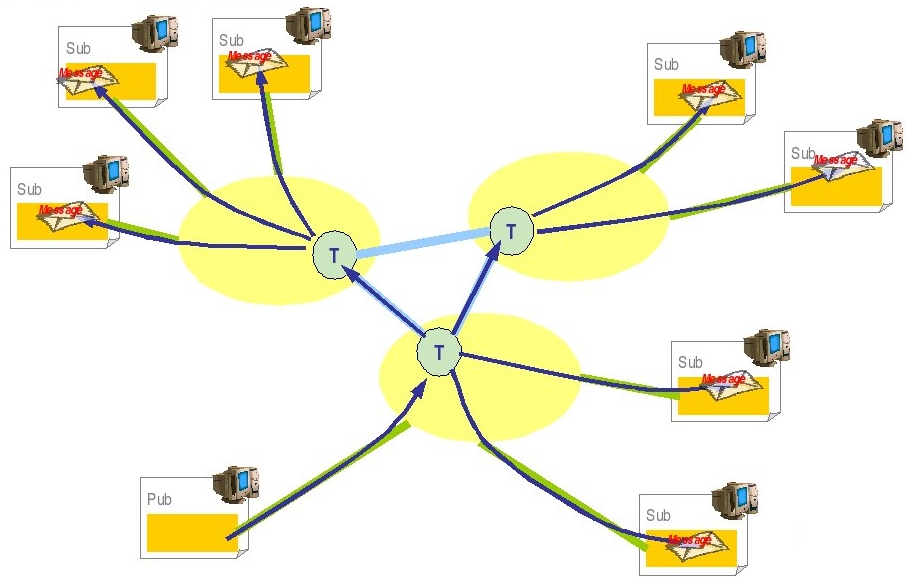 |
The following scenario and general settings are proposed:
The cluster topic is composed of two elements : mdbTopic1 defined hosted by JORAM server S1 and mdbTopic2 hosted by JORAM server S2.
The jndi name 'mdbTopic' is set for the local representative, ie mdbTopic1 for S1 et mdbTopic2 for S2.
At the server side, a MDB is listening the local representative 'mdbTopic'.
A client connects to the J1 or J2 server and sends 10 messages to the topic 'mdbTopic'.
Each message is received twice, one per cluster element.
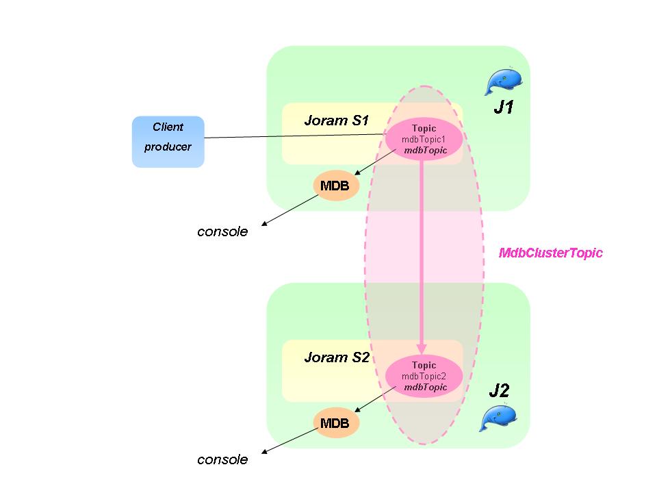 |
The cluster definition with the topics must be added in $JONAS_BASE/conf/joramAdmin.xml file. The connection factories and the anonymous user must be defined with the local server id and the local server port number according to the a3servers.xml content. Here only the cluster related elements are shown:
-
For the server id 1 :
Example 3.16. Cluster topic with JORAM
  <Topic name="mdbTopic1" serverId="1">
    <freeReader/>
    <freeWriter/>
    <jndi name="mdbTopic"/>
  </Topic>

  <Topic name="mdbTopic2" serverId="2">
    <freeReader/>
    <freeWriter/>
    <jndi name="mdbTopic2"/>
  </Topic>

  <ClusterTopic>
      <ClusterElement name="mdbTopic1" location="s1"/>
      <ClusterElement name="mdbTopic2" location="s2"/>
      <jndi name="clusterMdbTopic"/>
  </ClusterTopic>
-
For the server id 2 :
  <Topic name="mdbTopic1" serverId="1">
    <freeReader/>
    <freeWriter/>
    <jndi name="mdbTopic1"/>
  </Topic>

  <Topic name="mdbTopic2" serverId="2">
    <freeReader/>
    <freeWriter/>
    <jndi name="mdbTopic"/>
  </Topic>

  <ClusterTopic>
    <ClusterElement name="mdbTopic1" location="s1"/>
    <ClusterElement name="mdbTopic2" location="s2"/>
    <jndi name="clusterMdbTopic"/>
  </ClusterTopic>
|
Note |
|---|---|
|
The mdbTopic jndi name is bound in the local JOnAS registry with the local cluster element, i.e. mdbTopic1 for server id 1 and mdbTopic2 for server id 2. |
|
Note |
|---|---|
|
The joramAdmin.xml file has to be loaded when all cluster members are started since some remote cluster elements are defined. An alternative consists in splitting the configuration into two different files joramAdmin-local.xml and joramAdmin-cluster.xml, the first one containing only the local elements and the second one, both local and remote elements. At the JOnAS starting, a script could copy the right file to joramAdmin.xml according to the others members presence (joramAdmin-local.xml if it's the first member which starts and joramAdmin-cluster.xml if all the cluster members are started). |
The @MessageDriven annotation is updated in the source code for binding the MDB with the clustered topic. That could be done
through the optional deployment descriptor as well.
@MessageDriven(activationConfig = {
        @ActivationConfigProperty(propertyName ="destination", propertyValue ="mdbTopic"),
        @ActivationConfigProperty(propertyName ="destinationType", propertyValue ="javax.jms.Topic")
        }
)
The client code for sending a message to a Topic is used and the topic name is set to:
private static final String SAMPLE_TOPIC = "mdbTopic";
Deploy the MDB application in each JOnAS instance and run the sample. The messages do appear on the two different JOnAS servers consoles that shows the messages broadcasting between the topic elements.
Globally, the load balancing in the context of queues may be meaningless in comparison of load balancing topic. It would be a bit like load balancing a stateful session bean instance (which just requires failover). But the JORAM distributed architecture enables :
equilibrating the load of the queue access between several JORAM server nodes, it's a queue load-balancing at the server side.
load-balancing the load at the client side.
Here is a diagram of what is going to happen for the Queue and the message:
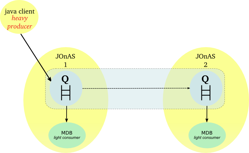 |
A load balancing message queue may be needed for a high rate of messages. A clustered queue is a cluster of queues exchanging messages depending on their load. The example has a cluster of two queues. A heavy producer accesses its local queue and sends messages. It quickly becomes loaded and decides to forward messages to the other queue of its cluster which is not under heavy load.
For this case some parameters must be set:
period: period (in ms) of activation of the load factor evaluation routine for a queue
producThreshold: number of messages above which a queue is considered loaded, a load factor evaluation launched, messages forwarded to other queues of the cluster
consumThreshold: number of pending "receive" requests above which a queue will request messages from the other queues of the cluster
autoEvalThreshold: set to "true" for requesting an automatic revaluation of the queues' thresholds values according to their activity
waitAfterClusterReq: time (in ms) during which a queue that requested something from the cluster is not authorized to do it again
For further information, see the JORAM documentation here .
The scenario for Queue is similar to the topic one. A client sent messages to a queue in S1. MDB gets messages from each local cluster queue representative. After having sent a burst of messages to the server S1, the load distribution should occur and message should be moved to S2.
The Queue definition in $JONAS_BASE/conf/joramAdmin.xml file is as following :
-
For server 1
Example 3.17. Cluster queue with JORAM
<Queue name="mdbQueue1"
          serverId="1"
          className="org.objectweb.joram.mom.dest.ClusterQueue">
  <freeReader/>
  <freeWriter/>
  <property name="period" value="10000"/>
  <property name="producThreshold" value="50"/>
  <property name="consumThreshold" value="2"/>
  <property name="autoEvalThreshold" value="false"/>
  <property name="waitAfterClusterReq" value="1000"/>
  <jndi name="mdbQueue"/>
</Queue>

<Queue name="mdbQueue2"
          serverId="2"
          className="org.objectweb.joram.mom.dest.ClusterQueue">
  <freeReader/>
  <freeWriter/>
  <property name="period" value="10000"/>
  <property name="producThreshold" value="50"/>
  <property name="consumThreshold" value="2"/>
  <property name="autoEvalThreshold" value="false"/>
  <property name="waitAfterClusterReq" value="1000"/>
  <jndi name="mdbQueue2"/>
</Queue>

<ClusterQueue>
    <ClusterElement name="mdbQueue1" location="s1"/>
    <ClusterElement name="mdbQueue2" location="s2"/>
    <jndi name="mdbQueueCluster"/>
</ClusterQueue>
-
For server 2
<Queue name="mdbQueue1"
          serverId="1"
          className="org.objectweb.joram.mom.dest.ClusterQueue">
  <freeReader/>
  <freeWriter/>
  <property name="period" value="10000"/>
  <property name="producThreshold" value="50"/>
  <property name="consumThreshold" value="2"/>
  <property name="autoEvalThreshold" value="false"/>
  <property name="waitAfterClusterReq" value="1000"/>
  <jndi name="mdbQueue1"/>
</Queue>

<Queue name="mdbQueue2"
          serverId="2"
          className="org.objectweb.joram.mom.dest.ClusterQueue">
  <freeReader/>
  <freeWriter/>
  <property name="period" value="10000"/>
  <property name="producThreshold" value="50"/>
  <property name="consumThreshold" value="2"/>
  <property name="autoEvalThreshold" value="false"/>
  <property name="waitAfterClusterReq" value="1000"/>
  <jndi name="mdbQueue"/>
</Queue>

<ClusterQueue>
    <ClusterElement name="mdbQueue1" location="s1"/>
    <ClusterElement name="mdbQueue2" location="s2"/>
    <jndi name="mdbQueueCluster"/>
</ClusterQueue>
|
Note |
|---|---|
|
The joramAdmin.xml file has to be loaded when all cluster members are started since some remote cluster elements are defined. An alternative consists in splitting the configuration into two different files joramAdmin-local.xml and joramAdmin-cluster.xml, the first one containing only the local elements and the second one, both local and remote elements. At the JOnAS starting, a script could copy the right file to joramAdmin.xml according to the others members presence (joramAdmin-local.xml if it's the first member which starts and joramAdmin-cluster.xml if all the cluster members are started). |
The @MessageDriven annotation is set with the mdbQueue queue. That could be done
through the optional deployment descriptor as well.
@MessageDriven(activationConfig = {
        @ActivationConfigProperty(propertyName ="destination", propertyValue ="mdbQueue"),
        @ActivationConfigProperty(propertyName ="destinationType", propertyValue ="javax.jms.Queue")
        }
)
The client code for the Queue is used and the queue name is set to:
private static final String SAMPLE_Queue = "mdbQueue";
The loop number can be increased in order to generate some pending messages in the first server:
private static final int NUMBER_MESSAGES = 1000;
Deploy the MDB application in each JOnAS instance and run the sample. The messages do appear on the two different JOnAS servers consoles that shows the load-balacing at the server side.
The load-balancing is done at the client side. A server is selected randomly among the cluster members at the first message sending or through the 'location' java property. And then, for a given client, all the messages are sent to the same server unless the java property resetting.
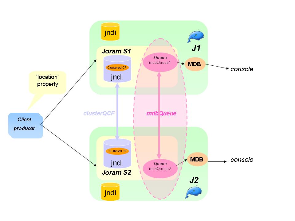 |
For setting the load-balancing at the client side, the client application must use a clustered connection factory that embeds the network connection parameters of the cluster members. This factory must be registered in the JORAM's distributed JNDI for ensuring that the client gets an up to date object. The main parameters are given below :
At first, the a3servers.xml file must enhanced with the JORAM's jndi service as following :
<?xml version="1.0"?>
<config>
  <domain name="D1"/>
  <property name="Transaction" value="fr.dyade.aaa.util.NTransaction"/>
  <server id="1" name="s1" hostname="localhost">
    <property name="location" value="s1" />
    <network domain="D1" port="16301"/>
    <service class="org.objectweb.joram.mom.proxies.ConnectionManager"
             args="root root"/>
    <service class="org.objectweb.joram.mom.proxies.tcp.TcpProxyService"
             args="16010"/>
    <service class="fr.dyade.aaa.jndi2.distributed.DistributedJndiServer"
               args="16401 1 2"/>
  </server>

  <server id="2" name="s2" hostname="localhost">
    <property name="location" value="s2" />
     <network domain="D1" port="16302"/>
     <service class="org.objectweb.joram.mom.proxies.ConnectionManager"
             args="root root"/>
    <service class="org.objectweb.joram.mom.proxies.tcp.TcpProxyService"
             args="16020"/>
    <service class="fr.dyade.aaa.jndi2.distributed.DistributedJndiServer"
               args="16402 2 1"/>
  </server>

</config>
|
Note |
|---|---|
| The location property is set for binding the MDB to the local queue instance. |
Only the JMS objects must be registered in the JORAM's jndi. The standard routing mechanism is used through a jndi.properties file put in each $JONAS_BASE/conf directory :
-
port number (16401 or 16402)
  java.naming.factory.url.pkgs    org.objectweb.jonas.naming:fr.dyade.aaa.jndi2
  scn.naming.factory.host         localhost
  scn.naming.factory.port         16402
The port number must be adapted according to the local server configuration (16401 for S1 and 16402 for S2). The 'scn' prefix is defined for identifying the objects to bind or to lookup in this registry.
The clustered connection factories are defined in the $JONAS_BASE/conf/joramAdmin.xml file as following :
<ConnectionFactory name="JQCF1" className="org.objectweb.joram.client.jms.tcp.QueueTcpConnectionFactory">
  <tcp host="localhost"
       port="16010"/>
  <jndi name="scn:comp/JQCF1"/>
</ConnectionFactory>
<ConnectionFactory name="JQCF2" className="org.objectweb.joram.client.jms.tcp.QueueTcpConnectionFactory">
  <tcp host="localhost"
       port="16020"/>
  <jndi name="scn:comp/JQCF2"/>
</ConnectionFactory>
<ClusterCF>
    <ClusterElement name="JQCF1" location="s1"/>
    <ClusterElement name="JQCF2" location="s2"/>
    <jndi name="scn:comp/clusterJQCF"/>
</ClusterCF>
The 'scn:comp/' prefix in the jndi name indicates that the object must be bound in the JORAM's jndi.
The cluster queue is defined in the $JONAS_BASE/conf/joramAdmin.xml file :
<Queue name="mdbQueue1" serverId="1"
       className="org.objectweb.joram.mom.dest.ClusterQueue">
   <freeReader/>
   <freeWriter/>
   <jndi name="scn:comp/mdbQueue1"/>
</Queue>

<Queue name="mdbQueue2" serverId="2"
       className="org.objectweb.joram.mom.dest.ClusterQueue">
   <freeReader/>
   <freeWriter/>
   <jndi name="scn:comp/mdbQueue2"/>
</Queue>

<ClusterQueue>
   <ClusterElement name="mdbQueue1" location="s1"/>
   <ClusterElement name="mdbQueue2" location="s2"/>
   <jndi name="scn:comp/mdbQueue"/>
</ClusterQueue>
|
Note |
|---|---|
The cluster queue definition is symetric across the cluster members. The well known jndi name is set on the cluster object (and not in the local representative as for the topic cluster). |
|
Note |
|---|---|
The joramAdmin.xml file has to be loaded when all cluster members are started since some remote cluster elements are defined. An alternative consists in splitting the configuration into two different files joramAdmin-local.xml and joramAdmin-cluster.xml, the first one containing only the local elements and the second one, both local and remote elements. At the JOnAS starting, a script could copy the right file to joramAdmin.xml according to the others members presence (joramAdmin-local.xml if it's the first member which starts and joramAdmin-cluster.xml if all the cluster members are started). |
The message driven bean must be configured with the queue registered in the JORAM jndi ('scn:/comp' selector).
The @MessageDriven annotation is set with the scn:/comp/mdbQueue queue.
That could be done through the optional deployment descriptor as well.
@MessageDriven(activationConfig = {
        @ActivationConfigProperty(propertyName ="destination", propertyValue ="scn:comp/mdbQueue"),
        @ActivationConfigProperty(propertyName ="destinationType", propertyValue ="javax.jms.Queue")
        }
)
The client must lookup the clustered objects in the JORAM's jndi by using the 'scn:/comp' selector. The client code for sending a message to a client is changed as following:
private static final String QUEUE_CONNECTION_FACTORY = "scn:comp/clusterJQCF";
private static final String SAMPLE_QUEUE = "scn:comp/mdbQueue";
The connection creation, session creation and producer are created like this:
        Queue queue = (Queue) initialContext.lookup(SAMPLE_QUEUE);
        Connection connection = ConnectionFactory.createConnection();
        Session session = connection.createSession(false, Session.AUTO_ACKNOWLEDGE);
        MessageProducer messageProducer = session.createProducer(queue);
A server is chosen at the first message sending. A switch may be forced through the resetting of the 'location' java property. Below a new server election is requested for each odd iteration.
        for (int i = 0; i < NUMBER_MESSAGES; i++) {
            message = session.createTextMessage();
            String text = "Message_" + i;
            message.setText(text);
            messageProducer.send(message);
            System.out.println("Message [" + message.getJMSMessageID() + ", text:" + text + "] sent");
            System.out.println("location=" + System.getProperty("location"));
            if (i%2 == 0) {
              System.setProperty("location", "");
            }
        }
        messageProducer.close();
        session.close();
        connection.close();
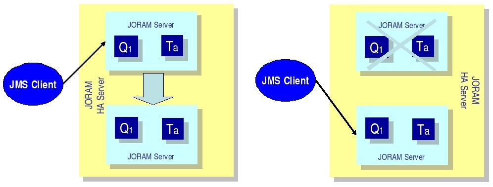 |
In JORAM terminology, an HA server is actually a group of servers, one of which is the master server that coordinates the other slave servers. An external server that communicates with the HA server is actually connected to the master server.
Each replicated JORAM server (element of the JORAM HA cluster, master or slave) executes the same code as a standard server except for the communication with the clients.
In the example, the collocated clients use a client module (MDB). If the server replica is the master, then the connection is active enabling the client to use the HA JORAM server. If the replica is a slave, then the connection opening is blocked until the replica becomes the master.
Several files must be changed to create a JORAM HA configuration:
A clustered server is defined by the element "cluster". A cluster owns an identifier and a name defined by the attributes "id" and "name" (exactly like a standard server). Two properties must be defined:
"Engine" must be set to "fr.dyade.aaa.agent.HAEngine" which is the class name of the engine that provides high availability.
"nbClusterExpected" defines the number of replicas that must be connected to the group communication channel used before this replica starts. By default it is set to 2. If there are more than two clusters, this specification must be inserted in the configuration file. If there are two clusters, this specification is not required.
In the case of one server and one replica, the value must be set to 1.
<?xml version="1.0"?/>
<config>
  <domain name="D1"/>

  <property name="Transaction" value="fr.dyade.aaa.util.NullTransaction"/>

  <cluster id="1" name="s1">

    <property name="Engine" value="fr.dyade.aaa.agent.HAEngine" />
    <property name="nbClusterExpected" value="1" />
For each replica, an element "server" must be added. The attribute "id" defines the identifier of the replica inside the cluster. The attribute "hostname" gives the address of the host where the replica is running. The network is used by the replica to communicate with external agent servers, i.e., servers located outside of the cluster and not replicas.
This is the entire configuration for the a3servers.xml file of the first JOnAS instance:
<?xml version="1.0"?>
<config<
  <domain name="D1"/>

  <property name="Transaction" value="fr.dyade.aaa.util.NullTransaction"/>

  <cluster id="1" name="s1">

    <property name="Engine" value="fr.dyade.aaa.agent.HAEngine" />
    <property name="nbClusterExpected" value="1" />

    <server id="1" hostname="localhost">
      <network domain="D1" port="16301"/>
      <service class="org.objectweb.joram.mom.proxies.ConnectionManager" args="root root"/>
      <service class="org.objectweb.joram.mom.proxies.tcp.TcpProxyService" args="16010"/>
      <service class="org.objectweb.joram.client.jms.ha.local.HALocalConnection"/>
    </server>

    <server id="2" hostname="localhost">
      <network domain="D1" port="16302"/>
      <service class="org.objectweb.joram.mom.proxies.ConnectionManager" args="root root"/>
      <service class="org.objectweb.joram.mom.proxies.tcp.TcpProxyService" args="16020"/>
      <service class="org.objectweb.joram.client.jms.ha.local.HALocalConnection"/>
    </server>

  </cluster>

</config>
The cluster id = 1 and the name S1. It is exactly the same file for the second instance of JOnAS.
Here is the joramAdmin.xml file configuration:
<?xml version="1.0"?>

<JoramAdmin>

<AdminModule>
  <collocatedConnect name="root" password="root"/>
</AdminModule>

<ConnectionFactory className="org.objectweb.joram.client.jms.ha.tcp.HATcpConnectionFactory">
  <hatcp url="hajoram://localhost:16010,localhost:16020"
            reliableClass="org.objectweb.joram.client.jms.tcp.ReliableTcpClient"/>
  <jndi name="JCF"/>
</ConnectionFactory>

<ConnectionFactory className="org.objectweb.joram.client.jms.ha.tcp.QueueHATcpConnectionFactory">
  <hatcp url="hajoram://localhost:16010,localhost:16020"
            reliableClass="org.objectweb.joram.client.jms.tcp.ReliableTcpClient"/>
  <jndi name="JQCF"/>
</ConnectionFactory>

<ConnectionFactory className="org.objectweb.joram.client.jms.ha.tcp.TopicHATcpConnectionFactory">
  <hatcp url="hajoram://localhost:16010,localhost:16020"
            reliableClass="org.objectweb.joram.client.jms.tcp.ReliableTcpClient"/>
  <jndi name="JTCF"/>
</ConnectionFactory>
Each connection factory has its own specification. One is in case of the Queue, one for Topic, and one for no define arguments. Each time the hatcp url must be entered, the url of the two instances. In the example, it is localhost:16010 and localhost:16020. It allows the client to change the instance when the first one is dead.
After this definition the user, the queue and topic can be created.
First, in order to recognize the cluster, a new parameter must be declared in these files.
      <config-property>
         <config-property-name>ClusterId</config-property-name>
         <config-property-type>java.lang.Short</config-property-type>
         <config-property-value>1</config-property-value>
      </config-property>
Here the name is not really appropriate but in order to keep some coherence this name was used. In fact it represents a replica so it would have been better to call it replicaId.
Consequently, for the first JOnAS instance, copy the code just above. For the second instance, change the value to 2 (in order to signify this is another replica).
Deploy the MDB application in each JOnAS instance and start them.
One of the two JOnAS bases (the one which is the slowest) will be in a waiting state when reading the joramAdmin.xml
JoramAdapter.start :   - Collocated JORAM server has successfully started.
JoramAdapter.start :   - Reading the provided admin file: joramAdmin.xml
whereas the other one is launched successfully.
Then launch the client:
Messages are sent on the JOnAS instance which was launched before. Launch it again and kill the current JOnAS. The second JOnAS will automatically wake up and take care of the other messages.
This is a proposal for building an MDB clustering based application.
The HA mechanism can be mixed with the load balancing policy based on clustered destinations. The load is balanced between several HA servers. Each element of a clustered destination is deployed on a separate HA server.
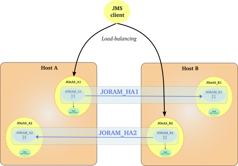 |
The configuration may now be tested, as follows:
First make JOnAS_A1 crash and verify that messages are spread between JOnAS_B1 and JOnAS_B2.
Then make JOnAS_B2 crash and verify that messages are spread between JOnAS_A1 and JOnAS_A2.
Finally make JOnAS_A1 and JOnAS_B2 crash and verify that messages are spread between JOnAS_A2 and JOnAS_B1.
A domain represents an administration perimeter which is under the control of an administration authority. It provides at least one common administration point for the elements in the domain.
A JOnAS domain may contain:
-
JOnAS instances or servers
-
groups of instances called clusters
-
cluster daemons, elements used for the remote control of instances and clusters
A common administration point is represented by a JOnAS instance having a particular configuration and playing the role of master. A master has the knowledge of the domain topology and allows executing administration operations on the rest of the servers and on the clusters. It also allows the monitoring of the domain elements.
The administered elements are identified by their names, that have to be unique within the domain, and the domain name.
Names can be defined in a static way, through the
domain.xml configuration file, or dynamically, by
starting new elements in the domain. For example, when starting a JOnAS
instance, the administrator can specify the server
name using the -n option and the domain
name by setting the domain.name environment
property. The uniqueness of the starting server's name is enforced by
the discovery service.
A domain configuration consists in the domain topology - the description of the elements composing the domain (servers, clusters, cluster daemons), and the state of the elements in the domain, as viewed from the common administration point.
The domain configuration dynamically evolves by starting or stopping servers and by creating or removing clusters in the domain.
The first step is to choose a name for the domain and to choose a server to represent the
common administration point. This server must be configured as a master by setting to true the
jonas.master property. Also, to allow dynamic domain management, add the discovery
service in the JOnAS services list (jonas.services
property) in jonas.properties file.
The domain name is not a configuration property for the master (neither for any server in the domain), but it has to be specified when starting the master.
Before starting the master, the administrator can define the
domain's initial topology by editing the domain.xml configuration file.
This step is optional. It consists in defining the domain elements
using the domain.xml configuration file located in
the master's configuration directory. If the administrator has no specific
configuration needs, it should at least check the name element,
and set its value to the chosen name. That file
can also be used to define a default user name and password (that may be encoded) to use when
connecting to servers and cluster daemons. Moreover, the administrator
can choose to remove the domain.xml file.
The elements that can be defined in domain.xml are:
-
server elements: allow to define a server in the domain, or a server in a cluster. A server has a name, a description, a location and optionally a user name and password as well as an associated cluster daemon. The location can be represented by a list of JMX remote connector server URLs.
-
cluster elements: allows to group servers in a logical cluster.
-
cluster daemon elements: allows to define a cluster daemon in the domain. A cluster daemon element has a name, a description, a location and optionally a user name and password. The location can be represented by a list of JMX remote connector server URLs.
Example 4.1. domain.xml
<?xml version="1.0" encoding="UTF-8"?>
<domain xmlns="http://www.objectweb.org/jonas/ns" xmlns:xsi="http://www.w3.org/2001/XMLSchema-instance" xsi:schemaLocation="http://www.objectweb.org/jonas/ns    http://www.objectweb.org/jonas/ns/jonas-domain_4_9.xsd">
  <name>sampleCluster2Domain</name>
  <description>A domain for sampleCluster2 servers management</description>

	<cluster-daemon>
		<name>cd</name>
		<description></description>
		<location>
		   <url>service:jmx:rmi://localhost/jndi/rmi://localhost:1806/jrmpconnector_cd</url>
		</location>
	</cluster-daemon>
	<cluster>
	   <name>mycluster</name>
	  <description>A cluster for sampleCluster2</description>
		<server>
		   <name>node1</name>
		   <location>
			<url>service:jmx:rmi://localhost/jndi/rmi://localhost:2002/jrmpconnector_node1</url>
		   </location>
		   <cluster-daemon>cd</cluster-daemon>
		</server>
		<server>
		   <name>node2</name>
		   <location>
			<url>service:jmx:rmi://localhost/jndi/rmi://localhost:2022/jrmpconnector_node2</url>
		   </location>
		   <cluster-daemon>cd</cluster-daemon>
		</server>
		<server>
		   <name>node3</name>
		   <location>
			<url>service:jmx:rmi://localhost/jndi/rmi://localhost:2032/jrmpconnector_node3</url>
		   </location>
		   <cluster-daemon>cd</cluster-daemon>
		</server>
		<server>
		   <name>node4</name>
		   <location>
			<url>service:jmx:rmi://localhost/jndi/rmi://localhost:2043/jrmpconnector_node4</url>
		   </location>
		   <cluster-daemon>cd</cluster-daemon>
		</server>
	</cluster>

</domain>
Start the master in the domain:
jonas start -n masterName -Ddomain.name=domainName
Note that the domain name is specified by setting a
domain.name environment property.
Once started, the administrator can manage and monitor the following elements in the domain through JonasAdmin, or another JMX based administration application (such as jconsole), running on the master:
-
servers declared in the domain.xml file.
-
other servers already started in the domain having the discovery service enabled.
-
clusters declared in the domain.xml file.
-
clusters detected by the administration framework
-
cluster daemons declared in the domain.xml file.
The goal of the cluster daemon is to enable the remote control of the JOnAS clustered instances through a JMX interface.
In a cluster configuration, the cluster daemon is the bootstrap of the JOnAS instances.
There is at least one cluster daemon instance per machine.
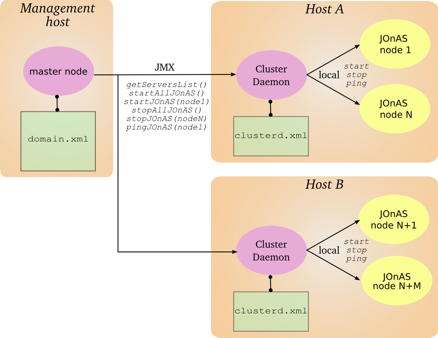 |
In the same manner as a classic JOnAS instance, the cluster daemon reads its configuration in a directory pointed to by a JONAS_BASE variable (or JONAS_ROOT if JONAS_BASE is not set). All the default JONAS_BASE subdirectories and files are not required; the mandatory ones are:
| element | description |
|---|---|
| $JONAS_BASE/conf | Configuration directory |
| $JONAS_BASE/logs | Log directory |
| $JONAS_BASE/conf/carol.properties | Carol configuration file describing the protocol and its parameters (used for the JMX interface) |
| $JONAS_BASE/conf/trace.properties | Trace/Error log configuration file |
| $JONAS_BASE/conf/jonas.properties | This file must be present for enabling the cluster daemon starting but its content is not read, the file can be empty |
| $JONAS_BASE/conf/clusterd.xml | Cluster daemon configuration file, lists the local JOnAS instances and describes their environment (see below) |
The JOnAS instances controlled by a cluster daemon are configured in the
clusterd.xml
file.
<?xml version="1.0"?>
<cluster-daemon xmlns="http://www.ow2.org/jonas/ns"
    xmlns:xsi="http://www.w3.org/2001/XMLSchema-instance"
    xsi:schemaLocation="http://www.objectweb.org/jonas/ns
    http://www.ow2.org/jonas/ns/jonas-clusterd_4_8.xsd">

   <name>cd1</name>
   <domain-name>domainSample</domain-name>
   <jonas-interaction-mode>loosely-coupled</jonas-interaction-mode>

   <server>
      <name>node1</name>
      <description>Web instance</description>
      <java-home>/usr/java/jdk-ia32/sun/j2sdk1.4.2_10</java-home>
      <jonas-root>/home/pelletib/pkg/jonas_root_sb48</jonas-root>
      <jonas-base>/home/pelletib/tmp/newjc48/jb1</jonas-base>
      <xprm></xprm>
      <auto-boot>false</auto-boot>
      <jonas-cmd></jonas-cmd>
   </server>

...

</cluster-daemon>
| Element | Description |
|---|---|
| name | Cluster daemon instance name. Used for building the connector url. |
| domain-name | Domain name to use for launching the JOnAS instance when it is not specified in the start command |
| jonas-interaction-mode |
Starting mode of the JOnAS instances:
loosely-coupled
corresponds to background and
tighly-coupled
corresponds to foreground. Typically, when launching in tighly coupled mode a cluster daemon stopping will cause the stopping
of the managed JOnAS instance.
|
| server/name | Name of the JOnAS instance |
| server/description | Description of the JOnAS instance |
| server/java-home | JDK home directory to be used for launching the JOnAS instance |
| server/jonas-root | JOnAS binaries directory to be used for launching the JOnAS instance |
| server/jonas-base | JOnAS configuration directory to use for launching the JOnAS instance |
| server/xprms | JVM parameters to set when launching the JOnAS instance |
| server/auto-boot | If true, start the JOnAS instance when launching the cluster daemon |
| server/jonas-cmd | Optional parameter. If set, specifies the script to use for starting/stopping the JOnAS instance. This user script can set the required environment and perform some pre or post processing. By default, the jonas command is used. |
The cluster daemons must be specified and associated to the JOnAS instances in the
domain.xml
file for permitting the remote control of the cluster.
...
<cluster-daemon>
   <name>cd1</name>
   <description>cluster daemon 1</description>
   <location>
      <url>service:jmx:rmi://host/jndi/rmi://host:port/jrmpconnector_cd</url>
   </location>
</cluster-daemon>
...
<server>
  <name>node1</name>
  <cluster-daemon>cd1</cluster-daemon>
  ...
</server>
...
The JMX remote url of the cluster daemon respects the following syntax:
service:jmx:rmi://
host
/jndi/rmi://
host
:
port
/
protocol
connector_
name
with the following meanings:
- host
ip alias or ip address of the machine that hosts the cluster daemon (by default localhost, can be overridden through the carol.properties file)
- port
tcp listen port of the registry embedded in the cluster daemon (by default 1806, can be overridden through the carol.properties file)
- protocol
protocol used for accessing the JMX interface (by default irmi, can be overridden through the carol.properties file)
- name
cluster daemon instance name (defined in the clusterd.xml file)
The cluster daemon is started using the command
jclusterd
. The possible options are:
| option | description |
|---|---|
| start | Start the cluster daemon. |
| stop | Stop the cluster daemon. |
| -DdomainName | Domain name to be used for starting the JOnAS instance. This value is used when it is defined both here and in the clusterd.xml file. |
| -carolFile <my-carol.properties> | Path to the carol.properties file to be used. If not specified, the file is loaded from $JONAS_BASE/conf. If the file is not found, the default values (localhost, 1806, irmi) are used. |
| -confFile <my-clusterd.xml> | Path to the clusterd.xml file to load. If not specified, the file is loaded from $JONAS_BASE/conf. |
The cluster daemon provides a JMX interface that enables control of the JOnAS instances. The following operations are available:
| Operation | Description |
|---|---|
| String getServersList() | Return the list of JOnAS instances |
| int pingJOnAS(String name) | Ping a JOnAS instance identified by its name |
| void startJOnAS(String name, String domainName, String prm) |
Start a JOnAS instance identified by its name. The parameter
domainName
(optional) provides the capability to specify the domain name. The parameter
prm
(optional) provides the capability to set some JVM parameters.
|
| String startAllJOnAS(String domainName, String prm) |
Start all the JOnAS instances known in the cluster daemon configuration. The parameter
domainName
(optional) provides the capability to specify the domain name. The parameter
prm
(optional) provides the capability to set some JVM parameters.
|
| void stopJOnAS(String name) | Stop a JOnAS instance identified by its name |
| String stopAllJOnAS() | Stop all the JOnAS instances known in the cluster daemon configuration |
| String getJavaHome4Server(String name) | Get the JAVA_HOME defined for a JOnAS server |
| String getJonasRoot4Server(String name) | Get the JONAS_ROOT defined for a JOnAS server |
| String getJonasBase4Server(String name) | Get the JONAS_BASE defined for a JOnAS server |
| void reloadConfiguration() | Reload the configuration file of the cluster daemon |
| void addServer(String name, String description, String javaHome, String jonasRoot, String jonasBase) | Add a definition of a JOnAS instance to the cluster daemon configuration. The change is saved in the configuration file. |
| void removeServer(String name) | Remove a definition of a JOnAS instance in the cluster daemon configuration. The change is saved in the configuration file. |
| void modifyServer(String name, String description, String javaHome, String jonasRoot, String jonasBase) | Modify the definition of a JOnAS instance in the cluster daemon configuration. The change is saved in the configuration file. |
A cluster is a group of JOnAS instances. The servers within a cluster are called cluster members. A server may be a member of several clusters in the domain.
A cluster is an administration target in the domain: from the common administration point of view, the administrator may monitor the cluster or apply to it management operations like deploy or undeploy of applications.
There are two main cluster categories:
-
Clusters containing instances that are grouped together only to facilitate management tasks.
-
Clusters containing instances that are grouped together to achieve objectives like scalability, high availability or failover.
The clusters in the first category, called Logical Cluster, are created by the domain administrator based on his/her particular needs. The grouping of servers (the cluster creation) can be done even though the servers are running.
In the second case, the servers which compose a cluster must have a particular configuration that allows them to achieve the expected objectives. Once servers are started, the administration framework is able to automatically detect that they are cluster members, based on configuration criteria. Several cluster types are supported by the JOnAS administration framework. They correspond to the different roles a cluster can play:
-
JkCluster - allow HTTP request load balancing and failover based on the mod_jk Apache connector.
-
TomcatCluster - allow high availability at web level based on the Tomcat 5.5 session replication solution. Tomcat 6 will be supported soon.
-
CmiCluster - enable JNDI clustering and allows load balancing at EJB level, based on the CMI protocol
-
HaCluster - allow transaction aware failover at EJB level and stateful session bean replication.
-
JoramCluster - allow JMS destinations scalability based on the JORAM distributed solution.
-
JoramHa - allow JMS destinations high availability based on JORAM HA.
An administrator can create a cluster if he/she needs to group some servers into a single administration target. There is no predefined criteria to explicitly group servers for administration purpose.
Cluster names and topology can be defined in a static way, using the
domain configuration file domain.xml. Here is an
example allowing to create a cluster named mycluster in
sampleDomain domain, in which servers
node1 and node2 are grouped together
for administration purpose.
<domain xsi:schemaLocation="http://www.objectweb.org/jonas/ns
         http://www.objectweb.org/jonas/ns/jonas-domain_4_9.xsd">
<name>sampleDomain</name>
<description>A domain example</description>
  <cluster>
  <name>mycluster</name>
  <description>A cluster example</description>
    <server>
      <name>node1</name>
      <location>
        <url>service:jmx:rmi://myhost/jndi/jrmp://myhost:2002/jrmpconnector_node1</url>
      </location>
    </server>
    <server>
      <name>node2</name>
      <location>
        <url>service:jmx:rmi://myhost/jndi/jrmp://myhost:2003/jrmpconnector_node2</url>
      </location>
    </server>
  <cluster>
<domain>
Clusters can also be created dynamically via the JonasAdmin management console application running on the master.
The configuration of JkCluster is described in the clustering configuration chapter. This section explains how to make such a cluster manageable from a domain master node.
To allow cluster member discovery and dynamic cluster creation,
the workers.properties file required by mod_jk
should be copied to the master's JONAS_BASE/conf directory.
At start-up, the master reads the
workers.properties file content. For each balanced
worker it checks if there is a running server in the domain having the
appropriate configuration allowing the server to play that worker
role.
Suppose that the master detects a server in the domain
corresponding to worker1. Then, it constructs a JkCluster named
loadbalancer. This name is given by the load
balancer worker's name. At this time, the cluster is composed of one
member named worker1. The member name is given by the
balanced worker's name.
After a while, a new JOnAS server is started in the domain having
the configuration corresponding to the worker2. The
master detects the new member named worker2 and updates the cluster's
member list.
Here is the loadbalancer JkCluster with
workers started, as it appears in the jonasAdmin console of the master:
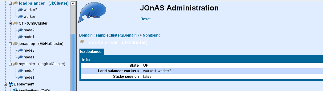 |
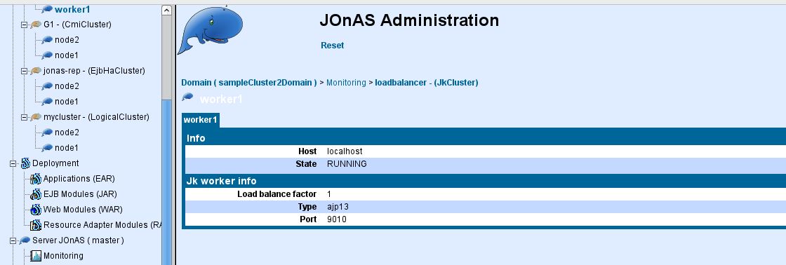 |
The configuration of TomcatCluster is described in the clustering configuration chapter.
|
Note |
|---|---|
|
the clusterName attribute is mandatory (and
not set by default in |
For example, lets consider the two JOnAS servers which play the role of
worker1 and worker2 in the
myloadbalancer JkCluster. Suppose
that these servers, named node1 and
node2 are configured as members of the
myTomcatCluster TomcatCluster. The
master detects automatically the Tomcat cluster membership and creates a
TomcatCluster named
myTomcatCluster. It adds node1 and
node2 to the cluster's member list.
Here is myTomcatCluster cluster with node1 and node2 members running, as it appears in the console
 |
The configuration of CmiCluster is described in the clustering configuration chapter.
The CMI cluster is automatically detected from the master node (CMI MBeans discovery). As a result, the following information is provided:
 |
CMI relies on JMX for its management. It provides a set of MBeans for retrieving management informations and performing some operations such as modifying the load-balancing logic.
All the CMI management is done at the server side and changes are propagated to the clients in a transparent way for the operator.
The CMI parameters are dynamic, the changes are taken into account in a near real-time (at the next refresh configuration period).
jonasAdmin provides a CMI management page which is accessible from any member in the CMI cluster by clicking on the server node in the navigation tree and by selecting the CMI tab.
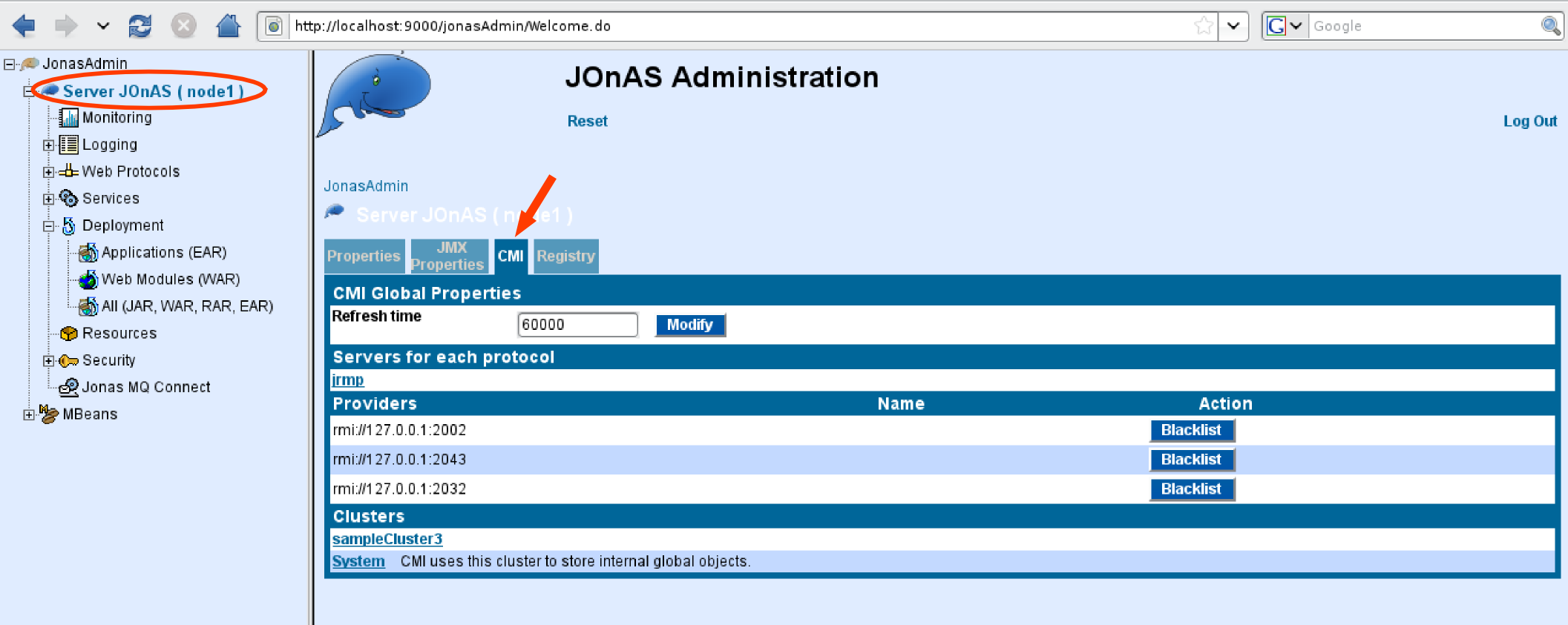 |
The page contains the following elements:
-
Global/Refresh time: specifies the client configuration refresh time period. When a policy changes or a parameter such as the load factor, the parameter indicates the maximum propagation delay to the client side.
-
Servers for each protocol: lists the servers in the cluster and the enabled protocols. More detailed information is delivered on the links.
-
Providers/Blacklist: disables smoothly a server in the cluster, i.e. new connections are refused whereas existing one are still served.
-
Clusters: lists the different cluster names. 'System' is a reserved cluster name gathering internal objects and is reserver for maintenance or advanced uses.
When selecting a cluster name in the bottom list, a new tab shows the clustered EJBs associated with this logical name:
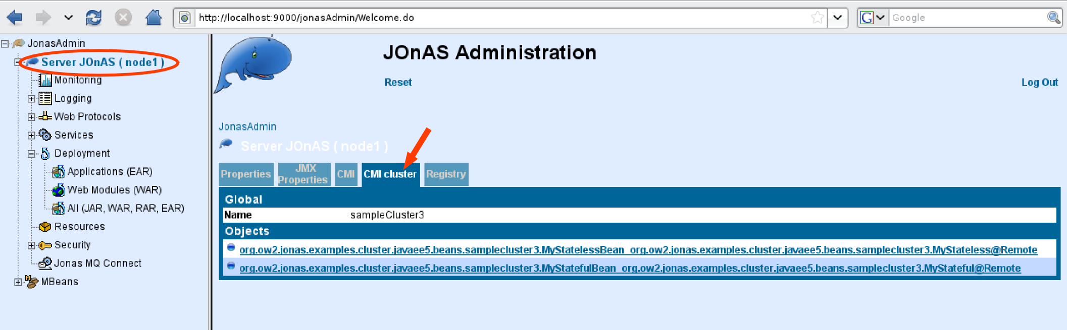 |
And then you can access to an object information page by clicking on a clustered EJB in the list:
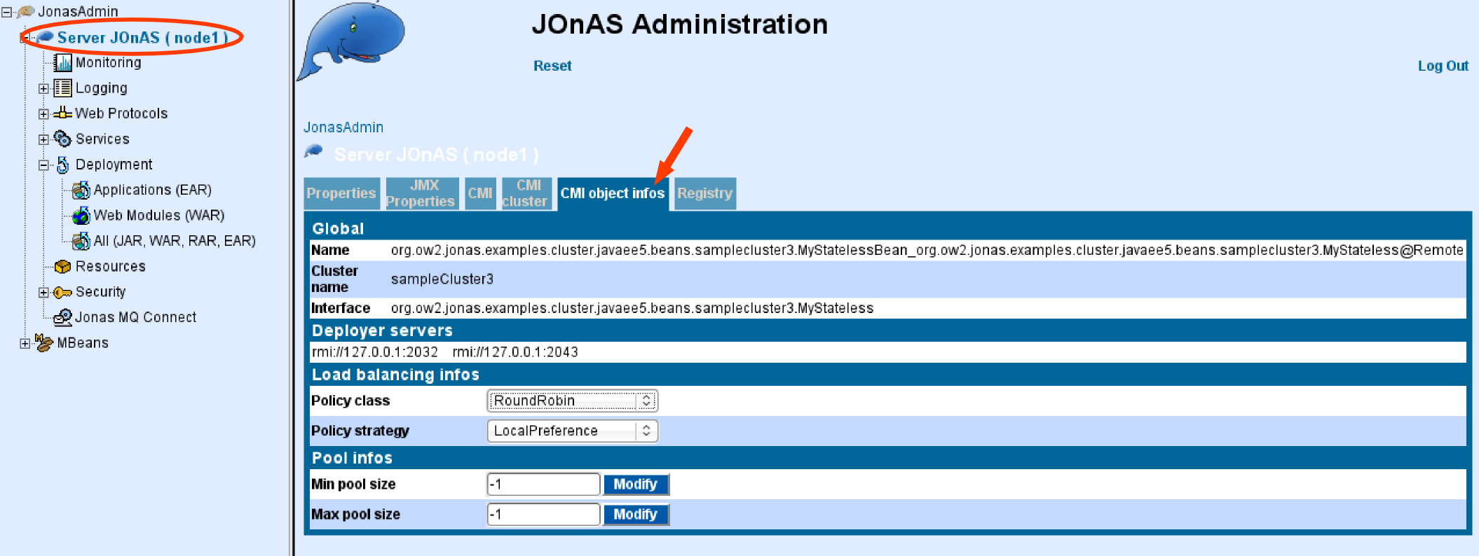 |
The page contains the following elements:
-
Global/Name: JNDI name of the clustered object.
-
Global/Cluster name: Cluster name associated with the clustered object.
-
Global/Interface: Interface class name of the clustered object.
-
Deployed server: List of servers where the clustered object is deployed.
-
Load-balancing infos: Policy and strategy of the clustered object.
-
Pool infos: Parameters of the stub pool associated with the clustered object.
Policies and strategies can be updated dynamically from jonasAdmin console.
From the clustered object information page, you can select another policy :
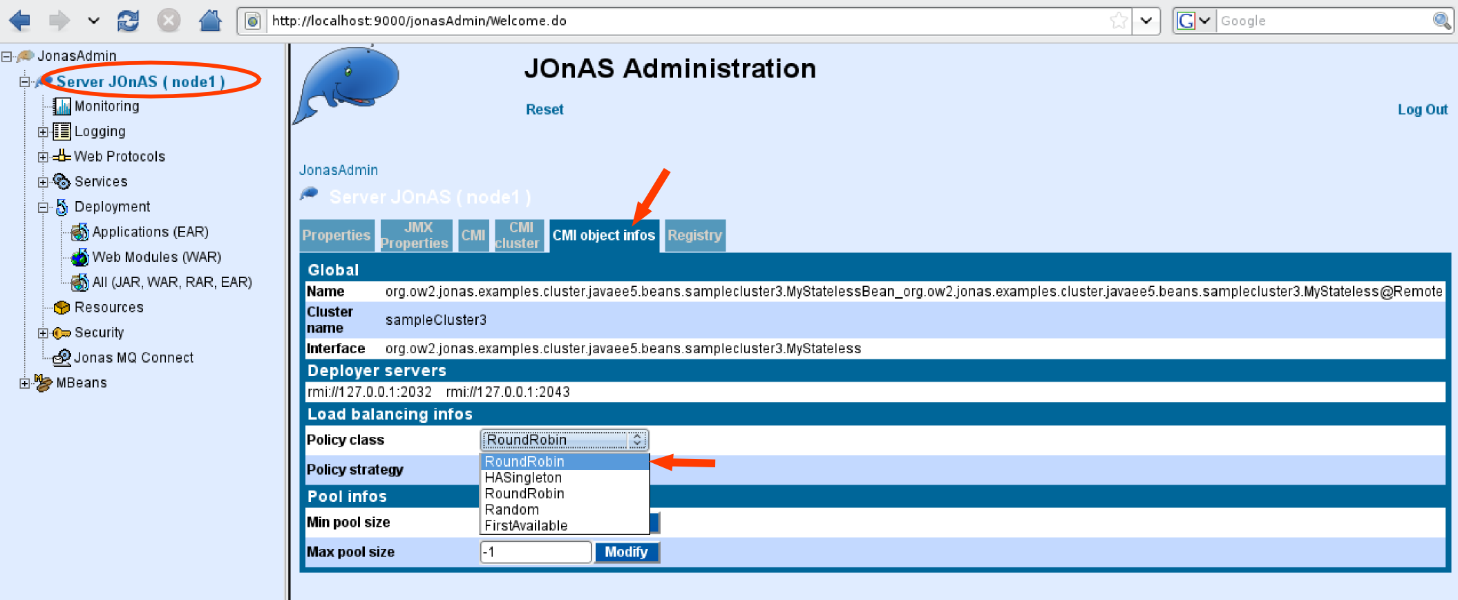 |
or strategy :
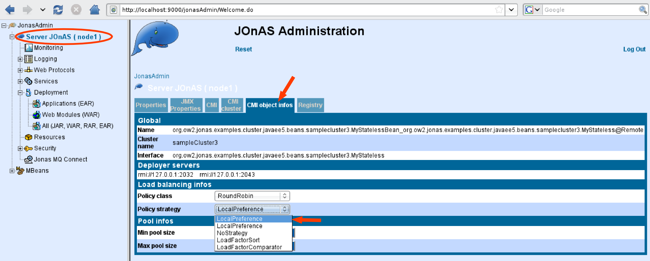 |
Refer to the Section 3.2.2.1.3.1, “Overview” section for more information.
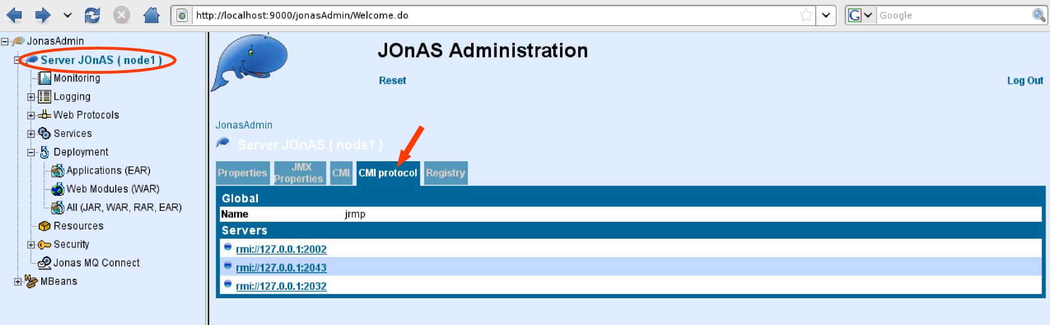
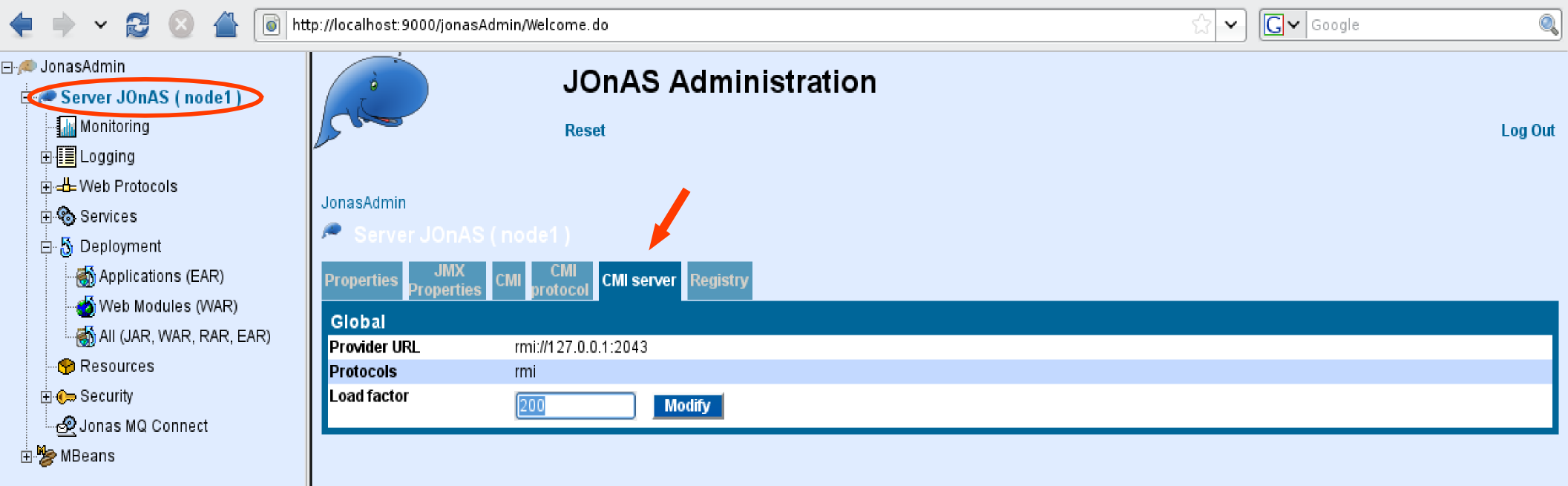
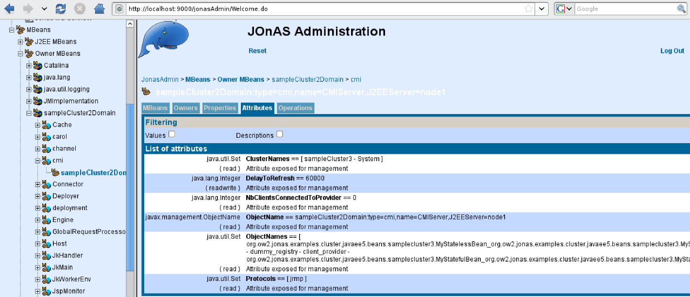
The JOnAS administration console offers to access several items of information about the HA service's replication algorithm and allows the configuring of several parameters related to its behavior. The related information and parameters include:
The name of the service.
The binded name for the MBean. The name can be changed.
The number of replicated messages sent by the algorithm to the cluster's replicas.
The average size of the replicated messages sent.
The total size of the replicated messages sent.
The current JGroups configuration file name used.
The current timeout established to clean memory information related to SFSBs required by the algorithm. When this timeout expires, the information is garbage-collected. This avoids increasing the memory used by the algorithm. The administrator can set a different timeout if required.
-
The datasource name required by the algorithm to keep track of current running transactions (See Transaction Table Configuration section above). The default datasource is set through the "jonas.service.ha.datasource" parameter in the "jonas.properties" configuration file, but the administrator can configure different datasources and can set here, the name of the one that will be used by the algorithm, once JOnAS has started.
Note It is recommended not to change the Datasource once the HA service is running.
Command that builds all the configurations (ie JONAS_BASE) of the JOnAS instances for the cluster (including also a JOnAS master to manage the domain, a JOnAS DB with an embedded HSQLDB server, and a cluster daemon). It also creates the configuration files needed for mod_jk.
The newjc utility builds all the configurations (ie JONAS_BASE) of the JOnAS instances for the cluster (including also a JOnAS master to manage the domain, a JOnAS db with an embedded HSQLDB server, and a cluster daemon). It also creates the configuration files needed for mod_jk.
At command start, the user must choose:
-
the cluster directory where the JOnAS configuration directories (ie JONAS_BASE) will be created,
-
the prefix for the new JOnAS configuration directories (ex: prefix jb generates jb1, jb2, ...),
-
the protocol among jrmp, iiop, irmi,
-
the database to configure for the
dbnode, -
the cluster architecture among bothWebEjb, diffWebEjb. The first means that all the nodes are configured with both web and ejb services whereas the second one will separate the two tiers,
-
the number of web instances,
-
the number of ejb instances.
The tool generates the configuration automatically but you can
customize some of the characteristics of the cluster by modifying the
following files, in JONAS_ROOT/conf/newjc, before
executing the command:
-
build-jc.properties: global configuration for the cluster, -
build-master.properties: specific configuration for the master node, -
build-db.properties: specific configuration for the db node.
If the -auto option is used, the
$JONAS_BASE variable must be set before launching the tool;
it specifies the prefix of the paths to the new directories that will be
built and that will contain the JONAS_BASE of the cluster members.
You can add some specific user configuration in the
$HOME/jc.config/lib. If the directory doesn't exits,
it will be created during the execution of the command.
A user configuration can be set in the
$HOME/jc.config/conf/jonas-newjc.properties file. If
this file is present, the parameters it contains will override the default
parameters defined in
JONAS_ROOT/conf/newjc/build-jc.properties.
newjc creates
tomcat_jk.conf and
workers.properties files under
<cluster-directory>/conf/jk. The #Web section
of build-jc.properties defines configuration
parameters set by newjc in these files. The file
tomcat_jk.conf contains apache directives supported
in httpd.conf or apache2.conf.
They are isolated in a separate file for modularity, then they must be
included manually in httpd.conf or
apache2.conf. Refer to workers HowTo
documentation on the Tomcat site.
newjc generates by default four JOnAS instances (four
JOnAS bases) in
directories jb1, jb2, jb3 and jb4 under the cluster directory. Each
JOnAS instance has
its own configuration files into the conf directory
(as any other JOnAS
base). It also generates configurations for cluster daemon
(cd directory), for master node
(master directory), and for db node
(db directory).
By default, jb1 and jb2 are JOnAS web container instances and jb3 and jb4 are JOnAS EJB container instances.
newjc generates a script called jcl4sc (jcl4sc.bat) for controlling the cluster examples provided with JOnAS named, sampleCluster2 and sampleCluster3. The command takes in argument the parameter status, start, stop, halt or kill.
The pertinent files for the configuration of the cluster are described below:
- carol.properties - jgroups-cmi.xml
-
The #Carol section of
build-jc.propertiesdefines configuration parameters set by newjc in thecarol.propertiesandjgroups-cmi.xmlfiles . This allows JNDI replication to support load balancing at the EJB level using the CMI protocol. - jonas.properties
-
The #Services section of
build-jc.propertiesdefines configuration parameters set by newjc in thejonas.propertiesfile. - tomcat6-server.xml
-
The #Web section of
build-jc.propertiesdefines some configuration parameters set by newjc in thetomcat6-server.xmlfile . In particular, a connector XML element for AJP1.3 protocol is defined, as well as a jvmRoute to support load balancing at the web level, via this connector.A Cluster XML element was also added. It defines parameters for achieving Session replication at the web level with JOnAS.
Refer to the AJP Connector and the Engine Container documentation.
Note The jvmRoute name generated by newjc is the same as the name of the associated worker defined in worker.properties. This will ensure the Session affinity.
To make apache aware of this new file, edit <prefix>/conf/httpd.conf.
Copy and paste the following line after the Dynamic Shared Object (DSO) Support section.
Include conf/jk/tomcat_jk.conf
Move the jk directory created by newjc under the APACHE structure:
bash> mv <cluster-directory>/conf/jk $APACHE_HOME/conf
Restart apache so that apache can load the jk_module:
bash> apachectl stop && apachectl start
|
Note |
|---|---|
|
Some UNIX distributions may locate the module in the folder libexec instead of the folder modules. |
JASMINe is an OW2 project (http://jasmine.ow2.org) aiming at developing an advanced administration tool for SOA platform and Java EE cluster. JASMINe supports both JOnAS 4 and JOnAS 5. JASMINe provides the following features :
-
JASMINe Design: a GUI tool for building a distributed configuration such as JOnAS cluster and storing it into an EMF format.
-
JASMINe Deploy: framework for ensuring
-
the middleware deployment from a model built with JASMINe Design. The solution relies on Jade for the push mode. Jade is an open source framework for building autonomic system and provides a deploy functionality. Push mode means that the middleware is deployed from a centralized point (jade boot) towards a distributed infrastructure (set of jade nodes). In the push mode, the deployment is triggered by the centralized point whereas the deployment is controlled from the distributed infrastructure in the pull mode. Pull mode is supported through a script getting the configuration description through an URL.
-
the client migration between either different application versions hosted within a same JOnAS instance or different middleware instances distributed against different machines (virtual or not).
-
-
JASMINe Monitoring: set of tools for
-
monitoring the performance. A event processing infrastructure is provided for collecting and storing monitoring datas and for visualizing some indicators into a Web 2.0 console.
-
detecting errors. A rules engine is connected to the event infrastructure and enables to implement some error detections rules which may generates some alerts for notifying the operator when a fault is encountered.
-
-
JASMINe Self-Management: some autonomic managers which implement some self-healing and self-optimization operations. Examples of such rules are load-balancer optimizer according to the current node load or the memory leak recovery by a JVM reboot.
JASMINe Design enables to describe a distributed middleware configuration through a Eclipse EMF/GMF graphical interface. Typically you may define your JOnAS cluster configuration with an Apache frontal, some web level instances, some ejb level instances and a database. The tools provides some wizards for managing some resources such as the port numbers, the instance names and so on.
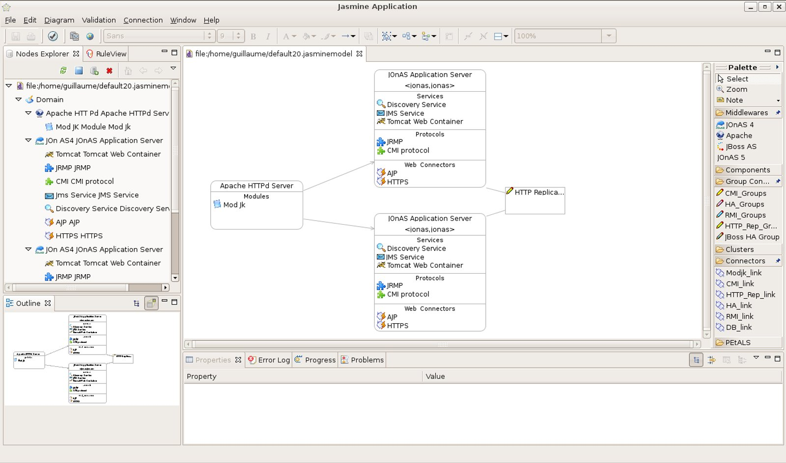 |
Once the configuration is built, JASMINe deploy is used for deploying it against a physical or virtual infrastructure.
See the JASMINe project web site for more detailed information and for getting the tool.
JASMINe Monitoring provides an infrastructure for supervizing a JOnAS distributed configuration with:
-
A JMX probe, named MBeanCmd, for collecting monitoring data through a JMX interface. Some built-in options are provided for getting some well-known application server indicators such as the transaction throughput or the current HTTP session number.
-
A events mediation infrastructure enabling to gather, aggregate, filter and store the monitoring events.
-
A Web 2.0 console (Eos console) enabling to track the performance into graphics.
-
A rules engine providing to the user the capacity to implement its own policy administration rules for detecting errors.
 |
See the JASMINe project web site for more detailed information and for getting the tool.
Jk Manager is an administration tool (graphical interface and API) for the Apache mod_jk plugin providing :
-
some monitoring informations such as statistics and status about the workers.
-
some operations such as the smooth worker disabling.
See the Apache Tomcat Connector web site for getting and installing mod_jk.
Refer to Section 3.1.1, “Configuring a WEB farm with mod_jk” for information about the configuration.
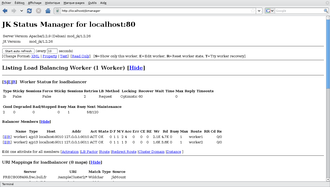 |
This example is delivered with JOnAS in the
JONAS_ROOT/examples/cluster-j2ee14 directory.
The sampleCluster2 application aims to demonstrate the JOnAS's clustering features in a “pedagogical” way for J2EE1.4.
These features are:
The application is composed of the following EJB 2.1 components:
-
1 SLSB (MyEjb1)
-
2 SFSB (MyStateful and MyStatefulInner)
-
1 EB
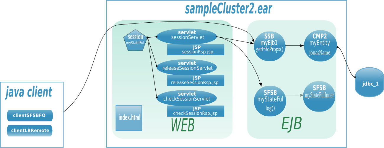 |
-
./bin-client: scripts to launch clients, -
./example-config: configuration example, -
./etc: configuration file, -
./src: source code. -
./output : generated ear, jar, war files.
First of all, configure the cluster using the newjc command. Please, refer to the newjc documentation and do not forget to install and configure apache2 as it's described in the Cluster Configuration Guide.
To build the application, launch ant tool from
JONAS_ROOT/examples/cluster-j2ee14 directory where
(the build.xml file is located).
-
ant enableLbMode ear for the load-balancing mode, or
-
ant enableHaMode ear earHA for the hight-avability mode.
|
Note |
|---|---|
|
By default, the SLSB calls are not integrated in the horizontal
algorithm. This default mode enables the load-balancing at the remote
interface. When the SLSB are marked as replicated in the
|
To start and halt the cluster, use the jcl4sc (jcl4sc.bat) command generated by newjc in the root of the JOnAS bases.
jcl4sc -c start allows to start the cluster, included the cluster daemon, the db node, the master node and the jbx nodes.
jcl4sc halt allows to halt the cluster.
You may type jcl4sc -help to get the usage of the command.
The sampleCluster2 application is automatically deployed on the cluster if you have previously build it, before using the jcl4sc command.
This example is delivered with JOnAS in the
JONAS_ROOT/examples/cluster-javaee5 directory.
The sampleCluster3 application aims to demonstrate the JOnAS's clustering features in a “pedagogical” way for Java EE 5.
These features are:
The application is composed of the following EJB3 components:
-
1 SLSB (MyStateless)
-
2 SFSB (MyStateful and MyStatefulInner)
-
1 EB (Node)
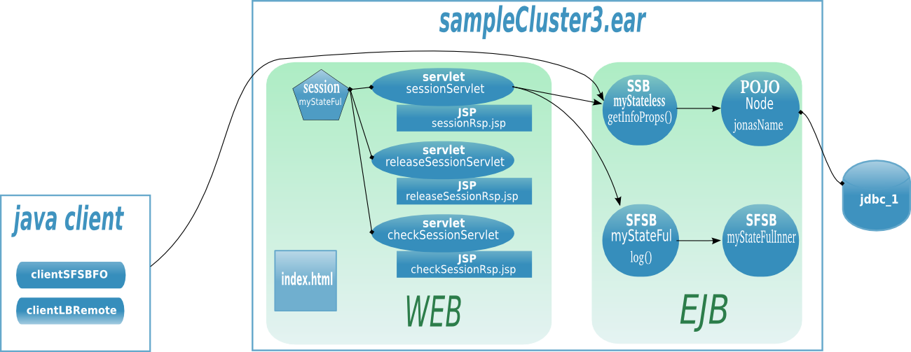 |
-
./bin-client: scripts to launch clients, -
./etc: configuration file, -
./example-config: configuration example, -
./src: source code, -
./output: generated files.
First of all, configure the cluster using the newjc command. Please, refer to the newjc documentation and do not forget to install and configure apache2 as it's described in the Cluster Configuration Guide.
To build the application, launch ant tool from
$JONAS_ROOT/examples/cluster-javaee5 root directory
where (the build.xml file is located).
-
ant ear. The application file
sampleCluster3.earis generated in./output/appsfolder.
To start and halt the cluster, use the jcl4sc (jcl4sc.bat) command generated by newjc in the root of the JOnAS bases.
jcl4sc -c start allows to start the cluster, included the cluster daemon, the db node, the master node and the jbx nodes.
jcl4sc halt allows to halt the cluster.
You may type jcl4sc -help to get the usage of the command.
The sampleCluster3 application is automatically deployed on the cluster if you have previously build it, before using the jcl4sc command.
No, CMIv2 relies on Carol V3.x and is not compliant with JOnAS 4. By the way CMIv2 requires JDK5 and higher.
No, new CMI (v2) is completely transparent for the client and doesn't require a pre-compilation step which is different from CMI v1 in JOnAS 4.
EJB application doesn't require any change provided that the application design is clustering safe. Typically static field must not be used. If no clustering annotation are set into the POJO, the specific deployment descriptor can be added for describing the load-balancing logic.
To select the right network interface, set your IP with the attribute bind_addr of the element UDP into the JGroups configuration files:
<config>
    <UDP bind_addr="192.168.0.1"
    ...
    />
...
</config>
JGroups 2.2 doesn't support IPv6. It must be disabled in the JVM
by setting the java.net.preferIPv4Stack to
true. JGroups 2.2 is used both in the
cmi and discovery services in JOnAS 4.
JOnAS 5 embeds JGroups 2.6 that supports quite well IPv6.
In JOnAS 4, when IPv6 is not disabled, the following exceptions may appear:
...
TP.down : failed sending message with java.io.IOException: Invalid argument
...
org.jgroups.ChannelException: failed to start protocol stack
Parameter setting example with linux/unix system:
export JAVA_OPTS="$JAVA_OPTS -Djava.net.preferIPv4Stack=true"
JGroups 2.2 doesn't support JDK6. The problem is due to the JDK
and is documented by Sun
here. JGroups is used both in the cmi, ha and
discovery services in JOnAS 4.
In a configuration JOnAS 4/JDK6, the following exceptions may appear:
...
org.jgroups.ChannelException: failed loading class
...
The workaround consists in setting the
sun.lang.ClassLoader.allowArraySyntax jvm property to
true. Example of such setting in a linux
system:
export JAVA_OPTS="$JAVA_OPTS -Dsun.lang.ClassLoader.allowArraySyntax=true"
This section describes the CMI use in a standalone mode (outside the application server).
The configuration occurs at two independent levels in CMI:
The configuration of the manager of the cluster view, needed only for servers ;
The configuration of the context, mandatory for all.
The manager of the cluster view can only be configured on the
server-side. The properties will be read from the file
cmi.properties when Carol is not used (see the
section dedicated to Carol for informations about it). The manager on
the client-side downloads dynamically its configuration. As a result,
all the managers on the client-side use the same configuration.
Here is the configuration relative at a server, common at all implementations:
# Class name of the implementation of the ServerClusterViewManager cmi.server.impl.class=org.ow2.cmi.controller.server.impl.jgroups.JGroupsClusterViewManager
|
Indicate a name for a concrete implementation of the
interface
|
|
Indicate a name of domain to register MBeans when CMI is in stand-alone. When CMI is used with Carol, the name of domain is provided by the latter. |
|
Indicate a name to register the MBean
|
|
Indicate for each protocol in the list, which JMX connectors will be bound into the registries. |
|
True indicates that a provider of the cluster view (for clients) will be bound for each protocol into the registries. |
|
True indicates that clients could use the registries of this server (for each protocol) to lookup objects that are not clustered. |
|
Indicate the load-factor of the associated server. |
Here is the configuration relative at a server, specific at the implementation with JGroups:
# Filename of the jgroups conf file cmi.server.impl.jgroups.conf=jgroups-cmi.xml
|
Indicate a filename that contains a stack to define a channel. |
|
Indicate a name of group to define a channel. |
|
Timeout to wait a reconnection. |
Configuring the context needs only several additional properties
(in comparison with the settings required to create a new instance of
javax.naming.InitialContext).
Here is the properties needed to generate the environment:
# Indicate a list of provider URLs cmi.context.provider.urls=rmi://129.183.101.165:1092,localhost:1099
|
Either a list of provider URLs (on servers) for a client (i.e. the property cmi.server.mode=false), or only one provider URL (on a local registry) for a server (i.e. the property cmi.server.mode=true). |
|
The class must implement the interface
|
|
Only one name of protocol is expected (while several can be set with Carol). |
|
If this property is set at true, a local registry to
perform writes (bindings for example) is expected. If this
property is set at false, a call at a writing operation will
throw an exception of type
|
|
True indicates that no instance of type
|
With its version 2.0.0, CMI is no more treated as a protocol. The result is that its configuration in Carol has changed.
Here is the properties relative to CMI, found in the file
carol.properties:
# jonas rmi activation (iiop, irmi, jrmp) carol.protocols=jrmp
|
Indicate a list of protocols to use. |
|
True indicates that CMI can be used (if enabled individually for each protocol). |
|
As in stand-alone mode, either a list of provider URLs (on servers) for a client, or only one provider URL (on a local registry) for a server. |
|
True indicates that CMI will be used for this protocol. If the property carol.start.cmi is set with the value false, this property is ignored. |
This chapter describes the use of CMI by users and administrators.
The first step in the use of CMI is the creation of the context. During this step the manager of the cluster view will be also constructed (if it doesn't already exist).
When CMI is used in stand-alone, the methods
getCMIEnv(),
getCMIEnv(URL) or
getCMIEnv(Properties) of the class
org.ow2.cmi.config.JNDIConfig must be used to
construct the environment that will be specified at the constructor
InitialContext(Hashtable<?, ?>) of
class javax.naming.InitialContext.
Here is an example of a construction of an instance of
org.ow2.cmi.jndi.context.CMIContext in
stand-alone:
Example A.1. Initializing the environment (from the file
cmi.properties) to construct a new
org.ow2.cmi.jndi.context.CMIContext
Hashtable<String, ?> cmiEnv = JNDIConfig.getCMIEnv();
InitialContext ic = new InitialContext(cmiEnv);
When CMI is associated with Carol, the configuration of the context is delegated to Carol, so no additional instruction is needed. The configuration of Carol will be explained in a next chapter.
Here is an example of a construction of an instance of
org.ow2.cmi.jndi.context.CMIContext with
Carol:
Example A.2. Initializing Carol with the file
carol.properties
ConfigurationRepository.init();
InitialContext ic = new InitialContext();
Likewise, the creation of an instance of
org.ow2.cmi.jndi.context.CMIContext can be
delegated to the smart factory.
The smart factory downloads transparently the missing classes and properties to use CMI. So, a client that uses it, doesn't need to have in its classpath the full library of CMI. Also, because properties (as the list of provider URLs) are downloaded before the creation of context, they are up-to-date.
The smart factory is enabled by an other implementation of the
interface
javax.naming.spi.InitialContextFactory.
So to use the smart factory, clients must specify the class
org.ow2.cmi.smart.spi.SmartContextFactory as
factory.
Here is an example of a construction of an instance of
org.ow2.cmi.jndi.context.CMIContext with the
smart factory:
Example A.3. Initializing the smart factory
Hashtable<String, Object> env = new Hashtable<String, Object>();
env.put(Context.INITIAL_CONTEXT_FACTORY, "org.ow2.cmi.smart.spi.SmartContextFactory");
env.put(Context.PROVIDER_URL, "smart://localhost:2505");
InitialContext ic = new InitialContext(env);
This section describes the steps in order to define new clustered objects.
A clustered object is characterized by its informations about clustering. They are of two kinds:
-
Declaration of a clustered object and its initial configuration;
The name of cluster containing this object is a part of the declaration.
The minimal and maximal sizes of the pool are a part of its initial configuration.
-
Description of the manner to access to it (the algorithm).
The policy and strategy of load-balancing are a part of the algorithm. While policy is mandatory to define the algorithm, strategy is optional.
CMI provides some standard policies and strategies. When an object is declared belonging to a cluster, the algorithm to access to it must be provided.
Standard policies:
Round robin
First available
Random
HA Singleton
Standard strategies:
Local preference
Load factor sort
Load factor weight
Designing a new algorithm consists in implementing interfaces.
To define its own policy, the following interface must be implemented:
Adding properties to a policy allows to add dynamicity at an algorithm, because properties are also downloaded by clients. The following section will describe how to declare these properties.
It exists two ways to add the informations about clustering:
-
Java annotations;
Annotations simplify the use of CMI by avoiding adding a new XML file. For the moment, only the class must be annotated and not its interface.
![[Warning]](../../resources/images/warning.png)
Warning A JDK 1.5 or higher is required to use annotations.
-
Deployment descriptors.
The source code is not modified, but a XML file is required.
Firstly the class of the clustered objects must be annotated
with @Cluster.
Here is the definition of this annotation:
Next, adding the annotation
@Policy permits to declare the way to
access to the instances of this class.
Here is the definition of this annotation:
Next, a strategy can be eventually used by annotating the
class with @Strategy.
Here is the definition of this annotation:
Finally, properties can be initialized by annotating the class
with @Properties.
Here is the definition of this annotation: